



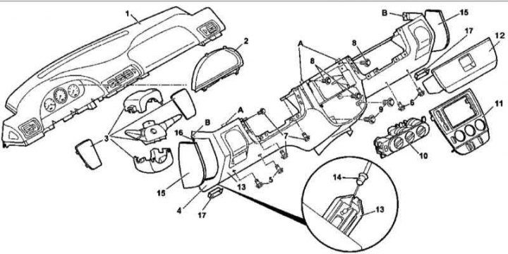
Lower Instrument Panel Section Installation Details (4)
5, 6 - Screws; 7-9 - Bolts; 12 - Glove box
1. The details of the installation of the lower section of the instrument panel are shown in the illustration to which all references in the text refer.
2. Move the selector lever to position "1" and support the wheels with wheel chocks.
3. Disconnect the negative cable from the battery.
4. Remove the steering column trim panels and the steering column switch assembly (3).
5. Turn inside out 1 (models produced up to 31.08.99)/3 (models produced since 01.09.99) mounting bolts (7).
6. Remove the lower left screws (5) securing the lower section of the instrument panel (4).
Original published on the website (MERCEDESMAN.ru)
7. Remove the center (console) section (11) of the instrument panel (see Section Removal and installation of the central (console) instrument panel sections).
8. Remove the heating / ventilation / air conditioning control panel (10).
9. Remove the mounting bolts (8 and 9).
10. Remove the glove box (see Sections Removal and installation the main storage compartment and Removal, installation and adjusting the main storage compartment cover (models produced up to 31.08.99)).
11. Remove the lower right screws (6) securing the lower section of the instrument panel (4).
12. Release the entrance illumination lights (17) from the instrument panel and remove them, having first disconnected the electrical wiring.
13. Remove the side trim panels (15) and unscrew the bolts (16) located underneath them.
14. Release the four fasteners (A) in the center of the lower section of the instrument panel (4).
15. Disconnect the drive cable (14) from the parking brake release handle (13).
16. Remove the lower section (4) of the instrument panel, being careful not to damage the instrument cluster.
17. Installation is carried out in the reverse order - make sure that the guide tabs (B) are seated correctly.
18. Finally, clear the memory of the on-board diagnostic system module (see Chapter Engine electrical systems).
Upper section
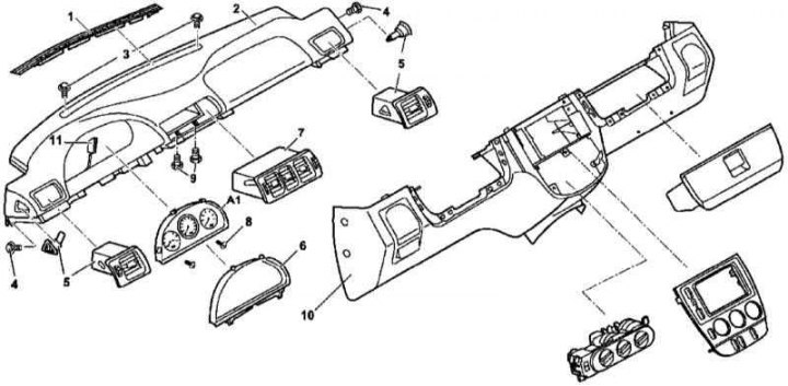
Upper Instrument Panel Section Installation Details
6 — Instrument cluster protective glass frame
8 - Plastic screws
1. The details of the installation of the upper section of the instrument panel are shown in the illustration to which all references in the text refer.
2. Remove the lower section (10) of the instrument panel (see above).
3. Remove the A-pillar trim panels (see Section Removal and installation body pillar trim panels).
4. Using a suitable wedge, remove the windshield air duct deflector (1), as well as the central (7) and side (5) deflector assemblies (see Section Removal and installation the instrument panel air duct deflectors).
5. Remove the two upper mounting screws (3).
6. Disconnect the contact connector (11) and remove the instrument cluster assembly (A1) (see Chapter On-board electrical equipment).
7. On models produced from 01.09.99, disconnect the electrical wiring from the solar radiation intensity sensor - the connector is located under the instrument cluster.
8. If equipped, remove the Parktronic system display.
9. On models produced from 01.09.99, disconnect the electrical wiring from the servomotor of the HVAC distribution flap drive - the contact connector is located on the left under the central deflectors assembly, and from the temperature sensor - the connector is on the right under the central deflectors assembly.
10. Remove the central (9) and side (4) mounting bolts and remove the upper section (2) of the instrument panel.
11. Installation is carried out in reverse order - try not to damage the instrument cluster.