
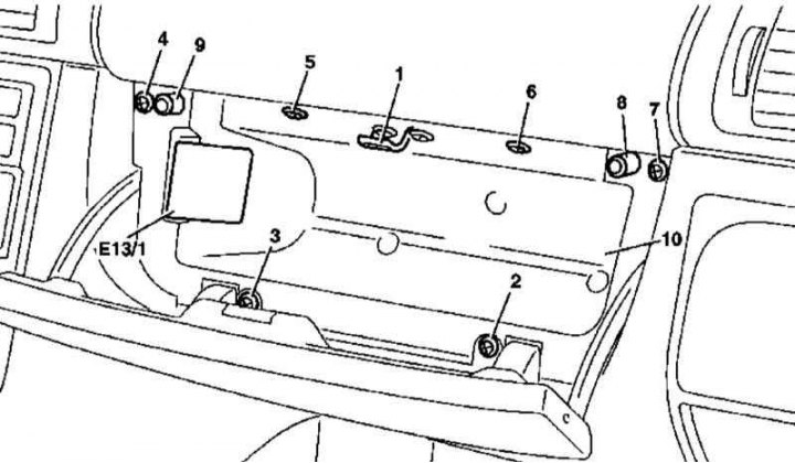
Main glove box installation details (models 163.136/154/172 with VIN according to A145272, X708318)
8, 9 - Buffer stops
1. Installation details of the main glove box version 1 (models 163.136/154/172 per A145272, per X708318) shown in the illustration, which includes all references in the text.
2. Open the drawer lid.
3. Release the drawer light from the latches (E13/1) and disconnect its wiring.
4. Remove the striker of the lock (1).
5. Remove the screws (2-7).
6. Prying from below, release the drawer (10) from the instrument panel.
7. Installation is carried out in the reverse order - check the proper functioning of the lock, if necessary, adjust the cover (see Section Removal, installation and adjustment of a cover of the main ware box (release models up to 08/31/99)).
Version 2
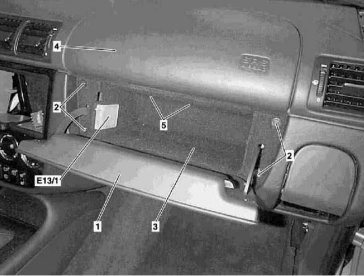
Main glove box installation details (models 163.113/128/157/174/175 and 163.136/154/172 with VIN with A145273, X708319)
1. Installation details of the glove box version 2 (models 163.113/128/157/174/175 and 163.136/154/172 with A145273, with X708319) shown in the illustration, which includes all references in the text.
2. Open the lid (1).
3. Release the drawer light from the latches (E13/1) and disconnect its wiring.
4. Remove the screws (2).
5. Remove the top blind rivets (5) glove box mounts (3), - to remove the rivet, press the 4 mm pin upwards and push the retainer body down.
6. Remove the glove box (3) from the dashboard (4).
7. Installation is carried out in the reverse order - make sure that the top edge of the cover is aligned correctly (1) with instrument panel (4).