
Cars BMW Cars Volkswagen Cars Chevrolet Cars Land Rover Cars Lada Cars Honda Cars Peugeot
English Русский
Български
Беларускі
Український
Српски
Hrvatski
Română
Polski
Slovenský
Magyar
Bookmark News and articles Sitemap Feedback Site search
MercedesMan.ru


A-Class C-Class E-Class G-Class M-Class S-Class Others
190 (W201) (1982-1993) W202 (1993-2000) W203 (2000-2007)
  • Main
  • C-Class
  • W201 (1982-1993)
  • Power unit
  • Ignition system (I4)
  • Ignition Control System Parts — Removal and Installation

Ignition Control System Parts — Removal and Installation (Mercedes-Benz C-Class W201)

0
Contents: Crankshaft speed sensor ↡ Electronic control unit (ECU) ↡ Coolant temperature sensor ↡ Throttle Position Sensor ↡ Incoming air temperature sensor ↡ TDC position sensor ↡

Crankshaft speed sensor


Removal


1. Disconnect the negative battery terminal.

2. Disconnect the sensor wire from the harness at the connector, which is located in the engine compartment behind the battery.

3. The sensor is located on the mating surface between the cylinder block and the clutch housing, above the starter hole. Loosen the mounting bolt and remove the sensor from the clutch housing. Remove the metal bushing where it is installed.

Installation


4. Installation is carried out in the reverse order. Where provided, before inserting the sensor into the housing, make sure that the bushing is installed.

Electronic control unit (ECU)


Removal


5. The ignition system control unit is located on the left side of the engine compartment, on top of the inner wheel arch (see Fig. 7.5, a, b).
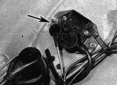
Fig. 7.5, a. Location of the electronic ignition control unit (shown by arrow) — models with TSZ…

Fig. 7.5, a. Location of the electronic ignition control unit (shown by arrow) — models with TSZ ignition system
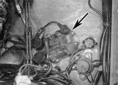

Fig. 7.5, b. Location of the electronic ignition control unit (shown by arrow) — models with EZL…

Fig. 7.5, b. Location of the electronic ignition control unit (shown by arrow) — models with EZL ignition system


6. Disconnect the negative battery terminal.


7. Disconnect the multi-pin connectors from the control unit, marking each one to avoid confusion during installation.

8. Disconnect the manifold vacuum hose from the fitting on top of the control unit. Plug the fitting to prevent dirt from getting into it.

9. Loosen the mounting nuts and remove the control unit from the engine compartment.

Note: The bottom of the control unit has a heat-conducting paste applied to it to improve cooling - try not to stain the surrounding parts with the paste. Do not remove the protective solder.


Installation


10. Installation is carried out in reverse order. If the contact paste layer is dirty or has hardened over time, purchase the required amount of paste from your Mercedes-Benz dealer and apply it again. Check that the protective layer is applied correctly.

Coolant temperature sensor


11. Where provided, the ignition system and fuel injection system share a common coolant temperature sensor - refer to the information provided in the relevant part of Chapter 4.

(Article based on data from the website: «MERCEDESMAN»)

Throttle Position Sensor


12. The ignition system shares a common throttle position sensor with the fuel system - refer to the information provided in the relevant section Chapters 4.

Incoming air temperature sensor


Removal


13. The incoming air temperature sensor is located on the side of the air cleaner housing.

14. Make sure the ignition is off. Then disconnect the sensor wires at the connector.

15. The sensor has a bayonet type connection - squeeze the tabs of the clamps, turn a quarter turn and remove it from the air cleaner. Remove the seal.


Installation


16. Installation is carried out in reverse order.

TDC position sensor


17. The TDC sensor is located on a bracket above the crankshaft vibration damper at the front of the engine. Installing the sensor with the bracket relative to the end of the vibration damper critically affects the operation of the ignition system and requires complex installation steps. For this reason, it is recommended that this work be performed at a service station.
This article is available at: russian, bulgarian, belarusian, ukrainian, serbian, croatian, romanian, polish, slovak, hungarian
The article has been verified: Lukyanov Nikita Ilyich
Share with friends:
◀ Previous
C-Class 190 (W201) / Ignition system (I4)
Next ▶

Ignition timing — checking and adjustment
Runner — removal and installation
Distributor — removal and installation
High Voltage Ignition Coil — Removal and Installation
Checking the ignition system
 
More similar articles for repairing other models

☛ General description of the ignition system Mercedes W168 (1997-2004)
☛ Ignition Control System Components — Removal and Installation Mercedes W124 (1984-1995)
☛ Checking the ignition and injection control system Mercedes W463 (1999-2019)
☛ Checking the ignition and injection control system Mercedes W163 (1997-2005)
☛ ME-SFI Fuel Injection and Ignition Control System Component Locations Mercedes W140 (1991-1998)
☛ Fuel injection and ignition control system HFM-SFI/MFI engine 104.900 Mercedes Vito 1 (1996-2003)
Link in different formats to this article
Comments and feedback from visitors
No comments yet


How much will 43 + 18 ?


W203 (2000-2007) 
  • General information
  • Introduction to guide
  • User manual
  • Maintenance
  • Power unit
  • Gasoline engines
  • Diesel engines
  • Cooling system
  • Ventilation and heating
  • Supply system
  • Injection system (gasoline)
  • Injection system (diesel)
  • Exhaust system
  • Ignition and control system
  • Charge and launch systems
  • Transmission
  • Mechanical gearbox
  • Automatic gearbox
  • Clutch and drive shafts
  • Differential
  • Chassis
  • Brake system
  • Car suspension
  • Steering
  • Body
  • Exterior (external elements)
  • Interior (internal elements)
  • Electrical equipment
  • Equipment and devices
  • Lighting system
  • Electrical diagrams (2000)
  • Electrical diagrams (since 2001)
W202 (1993-2000) 
  • General information
  • User manual
  • Driving a car
  • Car care
  • Maintenance
  • Power unit
  • Gasoline engines
  • Diesel engines
  • Lubrication system
  • Cooling system
  • Heating and ventilation
  • Ignition system
  • Fuel system
  • Injection system (gasoline)
  • Injection system (diesel)
  • Exhaust system
  • Transmission
  • Clutch
  • Car gearbox
  • Chassis
  • Suspension, wheels and tires
  • Steering
  • Brake system
  • Body
  • Exterior (external elements)
  • Interior (internal elements)
  • Doors and windows
  • Electrical equipment
  • Equipment and devices
  • Power devices
  • Lighting system
  • Electrical circuits
190 (W201) (1982-1993) 
  • General information
  • Introduction to the guide
  • Operation and care
  • Maintenance (gasoline)
  • Maintenance (diesel)
  • Troubleshooting
  • Power unit
  • Petrol engine I4
  • Petrol engine V6
  • Diesel engines
  • Engine overhaul
  • Cooling and heating
  • Power system (carburetor)
  • Injection system (gasoline)
  • Injection system (diesel)
  • Exhaust system
  • Charge and start system
  • Ignition system (I4)
  • Ignition system (V6)
  • Diesel heating system
  • Transmission
  • Clutch
  • Mechanical gearbox
  • Automatic gearbox
  • Cardan shaft and axle shafts
  • Chassis
  • Brake system
  • Car suspension
  • Steering
  • Body
  • Exterior (external elements)
  • Interior (internal elements)
  • Doors, locks and windows
  • Electrical equipment
  • Equipment and devices
  • Electrical circuits
 
MercedesMan.ru © 2017–2026 · Mobile version · Read about Mercedes · Sitemap: EN BG BY UA RS HR RO PL SK HU · Feedback · Site search · Bookmark A-Class (W168) · C-Class (W201) · C-Class (W202) · C-Class (W203) · E-Class (W123) · E-Class (W124) · E-Class (W210) · G-Class (W463) · M-Class (W163) · S-Class (W116, petrol) · S-Class (W126, petrol) · S-Class (W140) · S-Class (W220) · Sprinter · Vito 1 · Vito 2 · Vario 814D ·
 
We only use cookies without which some of the site's features may not be available.