
Cars BMW Cars Volkswagen Cars Chevrolet Cars Land Rover Cars Lada Cars Honda Cars Peugeot
English Русский
Български
Беларускі
Український
Српски
Hrvatski
Română
Polski
Slovenský
Magyar
Bookmark News and articles Sitemap Feedback Site search
MercedesMan.ru


A-Class C-Class E-Class G-Class M-Class S-Class Others
190 (W201) (1982-1993) W202 (1993-2000) W203 (2000-2007)
  • Main
  • C-Class
  • W201 (1982-1993)
  • Power unit
  • Ignition system (I4)
  • Distributor — removal and installation

Distributor — removal and installation (Mercedes-Benz C-Class W201)

0
Contents: Models with EZL type system ↡ Models with TSZ ignition system ↡

Models with EZL type system


Note: Unlike the TSZ contactless system, which is interrupted by a sensor inside the distributor, the EZL ignition system is switched exclusively by a position sensor on the crankshaft - the distributor's only function is to direct high voltage to the spark plugs. Therefore, the basic ignition timing settings cannot be changed by rotating the distributor housing. No ignition timing setting is required when installing the distributor.


Removal


1. Disconnect the negative battery terminal.

2. Loosen the mounting screws and remove the distributor cap and move it to the side.

3. Turn the crankshaft so that the piston of cylinder 1 is set to the TDC position, as described in Chapter 2A or 2B, depending on the engine type. After this, if you do not turn the crankshaft with the distributor removed from the cylinder block, you can remove and install the distributor without losing its alignment.

4. Loosen and remove the clamp bolt, then remove the distributor housing from the cylinder block (see fig. 4.4).
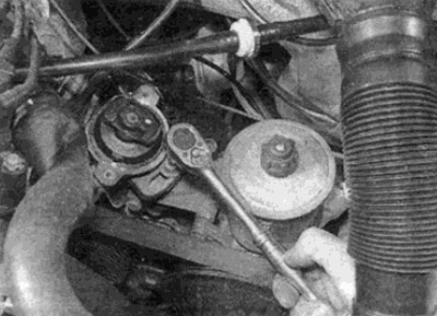
Fig. 4.4. Loosening the distributor clamp bolt

Fig. 4.4. Loosening the distributor clamp bolt


5. Check the condition of the oil seal ring (where it is installed) — if damage is detected or if oil leaks are detected, replace the ring.


Installation


6. If the crankshaft has not turned from the TDC position of the piston of the 1st cylinder, then perform the actions starting from step 8. If the position of the crankshaft has changed, perform the actions starting from step 7.

7. Remove the spark plug of cylinder 1 as described in Chapter 1 A. Block the spark plug hole with your thumb, then turn the crankshaft (as described in the "Removal" section) until the following conditions are met: (see fig. 4.7).
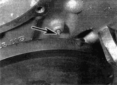
Fig. 4.7. The TDC position mark on the crankshaft vibration damper is aligned with the indicator…

Fig. 4.7. The TDC position mark on the crankshaft vibration damper is aligned with the indicator (shown by arrow) on the camshaft drive chain housing

  • a) There should be pressure felt in the spark plug hole.
  • b) The TDC mark on the crankshaft vibration damper must exactly match the pointer on the camshaft drive chain housing (see section 'Removal').

8. Insert the distributor into the crankcase and align the end of the distributor shaft with the drive gear so that:
  • a) When the distributor body is flush with the support flange, the runner will point directly at the alignment mark on the distributor body (temporarily remove the runner, then remove the plastic tap to see the alignment mark) (see Fig. 4.8, a, b).
  • b) The clamp bolt hole on the support flange is aligned with the center of the elongated hole on the distributor base. Rotate the distributor body to achieve this condition.
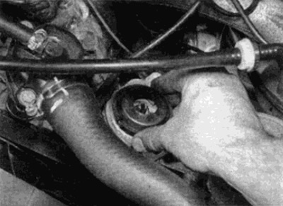
Fig. 4.8, a. Remove the plastic screen...
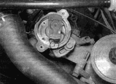
Fig. 4.8, a. Remove the plastic screen...


Fig. 4.8, b....to check that the runner points to the installation mark

Fig. 4.8, b....to check that the runner points to the installation mark


Note: The distributor pinion gear is helically cut, so the rotor will rotate when the distributor shaft is installed. To compensate for this, rotate the rotor to the timing mark before installing the distributor shaft.


9. Install the distributor clamp bolt and tighten securely.

10. Install the distributor cap, then insert and tighten the mounting screws.

Models with TSZ ignition system


Note: Unlike the EZL contactless ignition system which is interrupted by the crankshaft position sensor, the TSZ type ignition system is interrupted by a sensor fixed inside the distributor. Therefore, the basic ignition timing setting should be checked and adjusted after removing and installing the distributor.


Removal


11. Perform the actions described in paragraphs 1-3 inclusive.

12. Disconnect the hose from the vacuum unit on the side of the distributor housing.

13. Disconnect the distributor sensor wire from the connector side on the side of the distributor housing.

14. Mark the relative positions between the distributor base and the support flange on the engine using paint or a scraper. These marks will help you install the distributor correctly.

15. Loosen and remove the clamp bolt, then remove the distributor from the crankcase (see fig. 4.15).
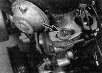
Fig. 4.15. Distributor clamp bolt (shown by arrow)

Fig. 4.15. Distributor clamp bolt (shown by arrow)


16. Check the condition of the oil seal ring (where it is installed) — if damage or oil leaks are detected, replace the ring.


Installation


17. Perform the actions described in points 6-10, inclusive (see fig. 4.17). To set the approximate ignition timing, use the marks made on the base of the distributor housing and the support flange during removal.
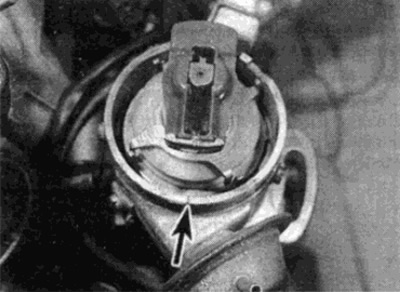
Fig. 4.17. The slider points directly to the alignment mark (shown by arrow) on the distributor body

Fig. 4.17. The slider points directly to the alignment mark (shown by arrow) on the distributor body


18. Connect the vacuum hose and sensor wire.

19. When finished, check and, if necessary, adjust the ignition timing, following the description in paragraph 6.
This article is available at: russian, bulgarian, belarusian, ukrainian, serbian, croatian, romanian, polish, slovak, hungarian
The article has been verified: Lukyanov Nikita Ilyich
Share with friends:
◀ Previous
C-Class 190 (W201) / Ignition system (I4)
Next ▶

High Voltage Ignition Coil — Removal and Installation
Checking the ignition system
Basic information about the ignition system
Technical data
Runner — removal and installation
Ignition timing — checking and adjustment
Ignition Control System Parts — Removal and Installation
More similar articles for repairing other models

☛ Installing the ignition distributor Mercedes W123 (1976-1985)
☛ Ignition distributor installation details Mercedes W140 (1991-1998)
☛ Scheme 2. Control system of a diesel engine with a distributor-type… Mercedes Sprinter (1995-2000, diesel)
Link in different formats to this article
Comments and feedback from visitors
No comments yet


How much will 19 + 17 ?


W203 (2000-2007) 
  • General information
  • Introduction to guide
  • User manual
  • Maintenance
  • Power unit
  • Gasoline engines
  • Diesel engines
  • Cooling system
  • Ventilation and heating
  • Supply system
  • Injection system (gasoline)
  • Injection system (diesel)
  • Exhaust system
  • Ignition and control system
  • Charge and launch systems
  • Transmission
  • Mechanical gearbox
  • Automatic gearbox
  • Clutch and drive shafts
  • Differential
  • Chassis
  • Brake system
  • Car suspension
  • Steering
  • Body
  • Exterior (external elements)
  • Interior (internal elements)
  • Electrical equipment
  • Equipment and devices
  • Lighting system
  • Electrical diagrams (2000)
  • Electrical diagrams (since 2001)
W202 (1993-2000) 
  • General information
  • User manual
  • Driving a car
  • Car care
  • Maintenance
  • Power unit
  • Gasoline engines
  • Diesel engines
  • Lubrication system
  • Cooling system
  • Heating and ventilation
  • Ignition system
  • Fuel system
  • Injection system (gasoline)
  • Injection system (diesel)
  • Exhaust system
  • Transmission
  • Clutch
  • Car gearbox
  • Chassis
  • Suspension, wheels and tires
  • Steering
  • Brake system
  • Body
  • Exterior (external elements)
  • Interior (internal elements)
  • Doors and windows
  • Electrical equipment
  • Equipment and devices
  • Power devices
  • Lighting system
  • Electrical circuits
190 (W201) (1982-1993) 
  • General information
  • Introduction to the guide
  • Operation and care
  • Maintenance (gasoline)
  • Maintenance (diesel)
  • Troubleshooting
  • Power unit
  • Petrol engine I4
  • Petrol engine V6
  • Diesel engines
  • Engine overhaul
  • Cooling and heating
  • Power system (carburetor)
  • Injection system (gasoline)
  • Injection system (diesel)
  • Exhaust system
  • Charge and start system
  • Ignition system (I4)
  • Ignition system (V6)
  • Diesel heating system
  • Transmission
  • Clutch
  • Mechanical gearbox
  • Automatic gearbox
  • Cardan shaft and axle shafts
  • Chassis
  • Brake system
  • Car suspension
  • Steering
  • Body
  • Exterior (external elements)
  • Interior (internal elements)
  • Doors, locks and windows
  • Electrical equipment
  • Equipment and devices
  • Electrical circuits
 
MercedesMan.ru © 2017–2026 · Mobile version · Read about Mercedes · Sitemap: EN BG BY UA RS HR RO PL SK HU · Feedback · Site search · Bookmark A-Class (W168) · C-Class (W201) · C-Class (W202) · C-Class (W203) · E-Class (W123) · E-Class (W124) · E-Class (W210) · G-Class (W463) · M-Class (W163) · S-Class (W116, petrol) · S-Class (W126, petrol) · S-Class (W140) · S-Class (W220) · Sprinter · Vito 1 · Vito 2 · Vario 814D ·
 
We only use cookies without which some of the site's features may not be available.