
Examination
1. If there is a problem with the system, the test consists of swapping with known-good components - however, before doing this, you can perform several preliminary checks, described below.
2. Connect a voltmeter or 12V test pump between the spark plug wire and a well grounded part of the engine.
Caution: Make sure the positive wire connection is not touching the body or engine.
3. Have an assistant turn on the heating system by turning the ignition key for a few seconds. At the same time, check the supply voltage supplied to the electrical contacts of the glow plugs.
Note: Initially, the supply voltage will be slightly less than the battery voltage, but it will grow and, when the candles warm up, will reach the voltage of the on-board network. Then, when the warm-up period ends and the trip occurs, the voltage drops to zero.
4. If there is no voltage at the glow plugs, the fault is either in the glow plug relay (where provided) or in the power cord.
5. To identify a faulty spark plug, first run the warm-up system to warm up the spark plugs to operating temperature, then disconnect the negative battery terminal.
6. Refer to the next subsection and remove the power cable from the spark plug terminal. Measure the electrical resistance between the spark plug terminal and engine ground. Values greater than a few ohms indicate that the candle is faulty.
7. If there is a high current ammeter, connect it between the spark plug and the power cable and determine the current flowing (ignore the initial surge of current, which can be as high as 50% of the current). Compare current ratings with those given in Technical Data - Higher Current Ratings (or no current) indicate a faulty spark plug.
8. As a final check, remove the spark plugs and inspect them as described in the relevant paragraphs.
Removing
9. Disconnect the negative battery terminal.
10. Loosen the nuts on the spark plug contacts. Remove cable connectors (see fig. 3.10). Please note that the nuts are fixed in the cable connectors.
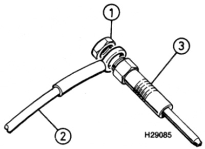
Pic. 3.10. Glow plugs and electrical connections
1 Terminal nut
2 Power cable
3 glow plug
11. Loosen and remove glow plugs (see fig. 3.11, a, b).
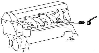
Pic. 3.11, a. Glow Plug Locations - Non-Turbo Engine
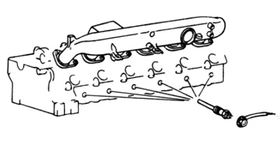
Pic. 3.11b. Glow Plug Locations - Turbocharged Engine
12. Check the glow plug probe for damage. A severely burned or sooty probe indicates a malfunction of the fuel injector; see Chapter 4 B for more information.
Installation
13. Installation is carried out in the reverse order, while tightening the glow plugs with the required torque.