



Contents: Four-cylinder petrol engines ↡ SOHC six-cylinder petrol engines ↡ Six-cylinder DOHC petrol engines ↡ Diesel engines ↡ Checking the working clearance of…↡ Installing pistons with connecting…↡
Four-cylinder petrol engines
To determine the required thickness of new connecting rod bearings, it is necessary to measure the inner diameter of the connecting rod bearing, the diameter of the crankshaft connecting rod journal and take into account the working clearance of the bearing. The required bearing thickness can be calculated as follows.
Example
Bearing diameter 62.51 mm
Crankshaft journal diameter 57.95 mm
4.56 mm
Bearing working clearance -0.04 mm
4.52 mm ±2
2.26 mm
Main bearing shells of the following thicknesses are supplied as spare parts.
| Inserts | Thickness of the liner |
| Nominal | 1.80 mm |
| Repair size 1 | 1.92 mm |
| Repair size 2 | 2.05 mm |
| Repair size 3 | 2.18 mm |
| Repair size 4 | 2.30 mm |
SOHC six-cylinder petrol engines
The thickness of the connecting rod bearing shells is determined in the same way as for 4-cylinder petrol engines. To determine the required shell size, please consult your Mercedes-Benz dealer.
Six-cylinder DOHC petrol engines
To determine the required thickness of new connecting rod bearings, it is necessary to measure the inner diameter of the connecting rod bearing, the diameter of the crankshaft connecting rod journal and take into account the working clearance of the bearing. The required bearing thickness can be calculated as follows.
Example
Bearing diameter 62.51 mm
Crankshaft journal diameter 57.95 mm
4.56 mm
Bearing working clearance -0.04 mm
4.52 mm ±2
2.26 mm
The required main bearing shell thickness should be determined from the table after consultation with your Mercedes-Benz dealer.
Diesel engines
To determine the required thickness of new connecting rod bearings, engines are required. To determine the required bearing size, consult your Mercedes-Benz dealer.
Checking the working clearance of connecting rod bearings
1. Clean the back of the bearing and where it fits into the connecting rod and connecting rod cap.
2. Install the liners into place.
3. One method, which requires a micrometer to measure the bore diameter, is to install the connecting rod bearing caps with the bearing shell onto the connecting rods and tighten them to the specified torque. Measure the inside diameter of each assembled pair of bearing shells. Measure the diameter of each crankshaft journal. Subtract the corresponding crankshaft journal diameter from the measured bearing diameter.
4. Second (and more accurate) the method is to use a product known as Plastigage. This is a round plastic rod that is compressed between the bearing shell and the crankshaft journal. After removing the connecting rod bearing cap, the deformed plastic rod is measured with a special template that is included with the Plastigage. The procedure for using Plastigage is as follows.
5. Install the connecting rods with bearings without lubrication on the crankshaft. The crankshaft journals and bearings must be completely clean and dry.
6. Cut a few pieces of Plastigage plastic rod (they should be slightly shorter than the width of the connecting rod bearings) and install on each crankshaft journal.
7. Install the caps with the lower liners and tighten the mounting bolts to the specified torque. Do not rotate the crankshaft during the Plastigage clearance measurement.
8. Unscrew the liner mounting cover, remove it and apply a scale ruler to the deformed plastic rod. By comparing the width of the deformed plastic rod with the control width on the scale ruler, determine the size of the gap.
9. Finally, thoroughly clean away any traces of Plastigage from the bearings and crankshaft.
Installing pistons with connecting rods
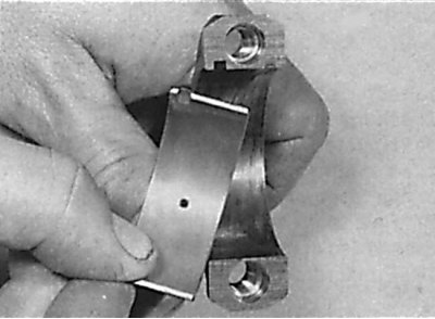
Installing the liner in the connecting rod cap
Protrusion under the piston crown on 6-cylinder DOHC gasoline engines
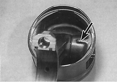
On 6-cylinder DOHC gasoline engines, the protrusion under the piston crown should be located on the flywheel side.
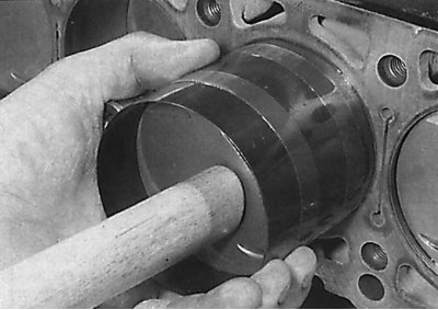
Installing a piston into a cylinder using a wooden block or hammer handle
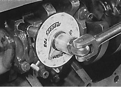
Tightening the connecting rod lower head cover bolts by turning them to a certain angle
1. Clean the back of the connecting rod bearing and the area where it fits into the connecting rods and connecting rod caps. Install the bearings into the connecting rods and connecting rod caps (see Fig. Installing the liner in the connecting rod cap).
2. Lubricate pistons and piston rings and position piston ring seals as required.
3. The installation of pistons should begin with the first cylinder. Compress the piston rings on the piston with a special device for compressing piston rings.
4. Insert the piston with the ring compressor into the top of the first cylinder, with the arrow on the piston bottom pointing toward the drive chain and the marks on the connecting rods and connecting rod caps in the same position as before removal (see fig. Protrusion under the piston crown on 6-cylinder DOHC gasoline engines). Using a wooden block or the handle of a hammer, push down on the piston and force it into the cylinder.
5. Check the alignment of the connecting rod lower head with the crankshaft journal. If necessary, tighten the piston with the connecting rod and install the connecting rod lower head with the insert on the crankshaft journal. Tighten the connecting rod cap mounting bolts to the required torque.
6. Install the remaining pistons and connecting rods in the same manner.
7. Further installation is carried out in the reverse order of removal, taking into account the following points.
8. On 4-cylinder gasoline engines, install the oil pan and cylinder head.
9. On 6-cylinder SOHC gasoline engines, install the oil pump, oil pan and cylinder head.
10. On 6-cylinder DOHC gasoline engines, install the oil pump, oil catch plate, oil pan and cylinder head.
11. On diesel engines, install the oil pump, oil catch plate, oil pan and cylinder head.