
Attention! Observe all necessary precautions related to the maintenance of A/C systems (see Section General information and security measures)!
Humidity sensor
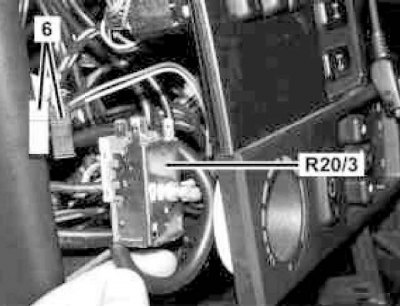
Installation details of the air humidity sensor (B31/2)
1. Open the hood.
2. Remove the air path resonator chamber with water collector (see chapter Power supply and exhaust systems).
3. Turn 45°in the direction shown by the arrow to remove the air humidity sensor (B31/2) and disconnect the wiring from it.
4. Installation is carried out in the reverse order - make sure that the sensor wiring does not get under the evaporator casing.
Refrigerant temperature and pressure sensor
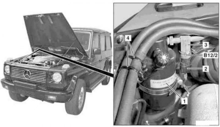
Refrigerant temperature and pressure sensor installation details
1. The need to replace this sensor arises when refrigerant leaks develop, as well as when the A/C system fails.
Attention! During the replacement of the sensor, do not allow moisture to enter the working circuit of the system!
2. Open the hood.
3. Remove the receiver dryer (1) (see Section Removal and installation of the receiver-drier), - Seal the open ends of the refrigerant lines immediately with suitable plugs.
Attention! The receiver-drier must be replaced without fail every time the working circuit of the A/C system is opened, - do not forget to take into account the volume of the receiver when refueling the system (see Specifications)!
4. Release the bandages (4) and move aside the coolant hoses.
5. Disconnect the wiring (2) from the temperature and pressure sensor of the refrigerant (B12/2).
6. Holding the pressure line from turning (3), unscrew and remove the sensor (B12/2).
7. Installation is carried out in the reverse order - do not forget to replace the sealing rings, lubricating them together with the threaded connections with compressor oil before installation.
8. In conclusion, check the proper functioning of the A/C system.
Evaporator temperature sensor
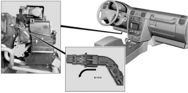
Evaporator Temperature Sensor Installation Details (B10/6)
1. On models of the corresponding configuration (code ET2) activate the service mode of the TELE AID emergency call system (see Section Activation / deactivation of the service mode of the TELE AID emergency call system).
2. Turn on the auxiliary and connect it to the original battery, then disconnect the negative cable from the battery.
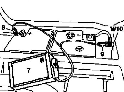
7 - Auxiliary battery
8 - Module positive wire terminal
9 - Terminal of the negative wire of the module
W10 - Battery Ground
3. Remove the cover on the left under the instrument panel (see chapter Body).
4. Pull in the direction of the arrow shown in the picture to remove the temperature sensor (B10/6) from the evaporator housing, then disconnect the electrical wiring from it.
5. Installation is carried out in the reverse order.
6. Finally, deactivate the service mode of the TELE AID system (see Section Activation / deactivation of the service mode of the TELE AID emergency call system) and clear the memory of the on-board self-diagnosis module (see chapter Engine Electrical Systems).