
Petrol models
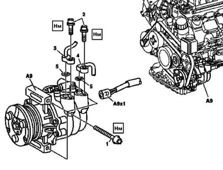
Details of installation of the compressor of system K/V on petrol models
1. Discharge the air conditioning system in a specialized service station.
2. Remove the fan accessory assembly (see Section Removing and Installing the Auxiliary Fan Assembly).
3. Remove the condenser of the A/C system (see Section Removal and installation of the condenser of system K/V).
4. Remove the radiator of the cooling system (see Section Removal and installation of a radiator of system of cooling).
5. Remove the accessory drive belt (see chapter Engine).
6. Disconnect the connector (А9x1) electric wiring of the K/V compressor.
7. Remove the screws (2) and remove the input (4) and pressure (3) lines of the refrigeration path, - immediately plug the open ends of the lines and connecting fittings to prevent moisture from entering the path, prepare replaceable sealing rings (5).
8. Remove the fixing screws (1) and remove the compressor assembly (A9) A/C systems.
9. Remove the dryer receiver assembly (see Section Removal and installation of the receiver-drier), - the receiver must be replaced without fail. Be sure to plug the open ends of the refrigeration lines.
10. Install in reverse order
Note. Mounting screws (1) must be filled in place before installing the compressor.
11. Make sure that the necessary (by the number of components replaced, see Specifications) amount of refrigerant oil. Do not forget to lubricate new O-rings with compressor oil before installation.
12. Start the engine and let it idle for about 4 minutes with the air conditioner turned on at maximum cooling capacity - the temperature of the air supplied to the passenger compartment through the central air vents on the instrument panel should not fall below + 5°С.
13. Make sure that there are no signs of the development of leaks from the refrigeration path.
Diesel models
G270 CDI (M612)
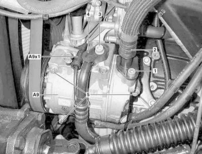
Details of installation of the compressor of system K/V on diesel models with the M612 engine
1. Empty the cooling system, in the conditions of a specialized service station, discharge the air conditioning system.
2. Remove the dryer receiver assembly (see Section Removal and installation of the receiver-drier), - the receiver must be replaced every time after opening the refrigeration path. Be sure to plug the open ends of the refrigeration lines.
3. Remove the cooling system radiator (see Section Removal and installation of a radiator of system of cooling).
4. On suitably equipped models (code H12) remove the auxiliary heater assembly (see Section Removal and installation of additional heater STH (with appropriate equipment)).
5. Remove the accessory drive belt (see chapter Engine).
6. Remove the left sleeve of a path of system of pressurization.
7. Disconnect the connector (А9x1) electric wiring of the K/V compressor.
8. Turn out fixing bolts (1 and 3) and remove the input (2) and pressure (4) lines of the refrigeration path, - immediately plug the open ends of the lines and connecting fittings to prevent moisture from entering the path, prepare replaceable sealing rings.
9. Turn out fixing bolts (5) and remove the compressor assembly (A9) A/C systems.
10. Installation is carried out in the reverse order.
Note. When installing a new compressor, slightly relieve pressure in it; the expansion valve, inlet and pressure lines with o-rings are also replaced with the compressor.
11. Correct the refrigerant level in the compressor, finally check the components of the refrigeration and cooling (models with code H12) paths for signs of leak development.
G400 CDI (M628)
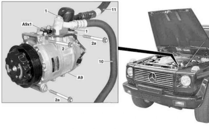
Details of installation of the K/V system compressor on diesel models with the M628 engine
1. Open the hood.
2. Empty the cooling system, in the conditions of a specialized service station, discharge the air conditioning system.
3. Remove the dryer receiver assembly (see Section Removal and installation of the receiver-drier), - the receiver must be replaced every time after opening the refrigeration path. Be sure to plug the open ends of the refrigeration lines.
4. Remove the condenser of the A/C system (see Section Removal and installation of the condenser of system K/V).
5. On suitably equipped models (code H12) remove the auxiliary heater assembly (see Section Removal and installation of additional heater STH (with appropriate equipment)).
6. Remove the accessory drive belt (see chapter Engine).
7. Remove the left lower air duct of the boost path.
8. Disconnect the connector (А9x1) electric wiring of the K/V compressor.
9. Remove the screws (1) and remove the input (11) and pressure (10) lines of the refrigeration path, - immediately plug the open ends of the lines and connecting fittings to prevent moisture from entering the path, prepare replaceable sealing rings.
10. Turn out fixing bolts (2 and 2a) and, pulling up, remove the compressor assembly (A9) A/C systems.
11. Installation is carried out in the reverse order.
Note. When installing a new compressor, slightly depressurize it; the inlet and pressure lines with o-rings are also replaced with the compressor.
12. Correct the level of refrigerant in the compressor, finally check the components of the refrigeration and cooling (models with code H12) paths for signs of leak development.