
Attention! Observe all necessary precautions related to the maintenance of A/C systems (see Section General information and security measures)! Removal and installation of the evaporator casing must be carried out by two people!
Evaporator cover
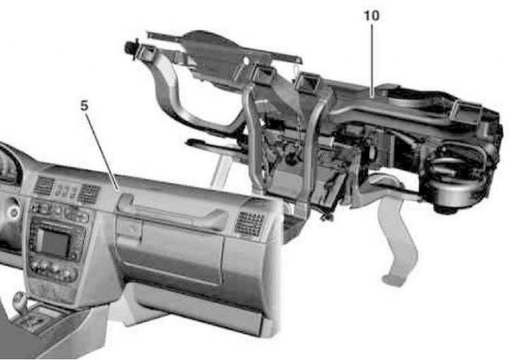
Details of installation of a casing of the evaporator of the K/V system (1 of 3)
5 - Instrument panel
10 - Evaporator casing
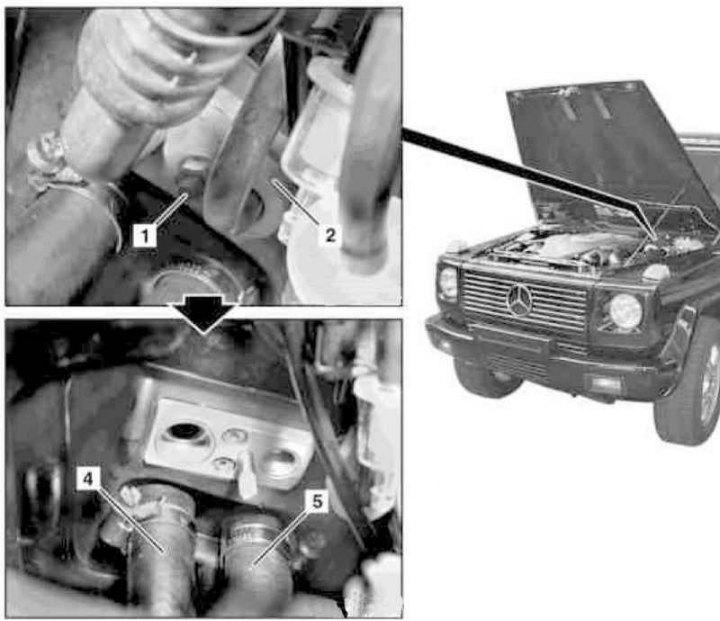
Details of installation of a casing of the evaporator of the K/V system (2 of 3)
1 - Nut
2 - Mounting plate
3 - Hot water supply hose
4 - Hot water return hose
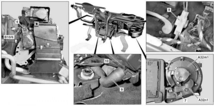
Details of installation of a casing of the evaporator of the K/V system (3 of 3)
6, 7, 8 - Connectors
9 - Drainage hose
10 - Evaporator casing
A32m1 - Fan drive electric motor
A32n1 - Fan controller
B10 / 6 - Evaporator temperature sensor
1. Open the hood.
2. After opening the cap, release the pressure in the cooling system, then drain the coolant (see chapter Ongoing care and maintenance).
3. Remove the dryer receiver assembly (see Section Removal and installation of the receiver-drier).
4. Give the nut (1) expansion valve mounting.
5. Remove pressure lines complete with fixing plate (2), - immediately seal the open ends of the lines to prevent moisture from entering the working path of the system, prepare replaceable sealing rings.
6. Remove the feeder from your necks (4) and return (5) heater hoses, - prepare suitable plugs.
7. Slide both front seats all the way back.
8. Remove the dashboard (see chapter Body).
9. Remove the gas pedal.
10. Remove the floor carpet in the driver's footwell.
11. Remove the left air supply hose to the rear of the passenger compartment.
12. Disconnect the connector (6) evaporator temperature sensor wiring (B10/6).
13. Remove the ignition control module (see chapter Power supply and exhaust systems).
14. Disconnect connectors (7 and 8).
15. Using a suitable tool, remove the drain hoses (9).
16. Remove the support brackets securing the evaporator casing to the A-pillar, floor panel, and bulkhead.
17. Remove the evaporator cover (10).
18. Installation is carried out in the reverse order. New O-rings should be lubricated with compressor oil before installation.
19. In conclusion, clear the memory of the processor of the on-board self-diagnosis system and synchronize the stepper motors of the actuator drive using the STAR DIAGNOSIS reader (contact a Mercedes-Benz service station for help).
Evaporator
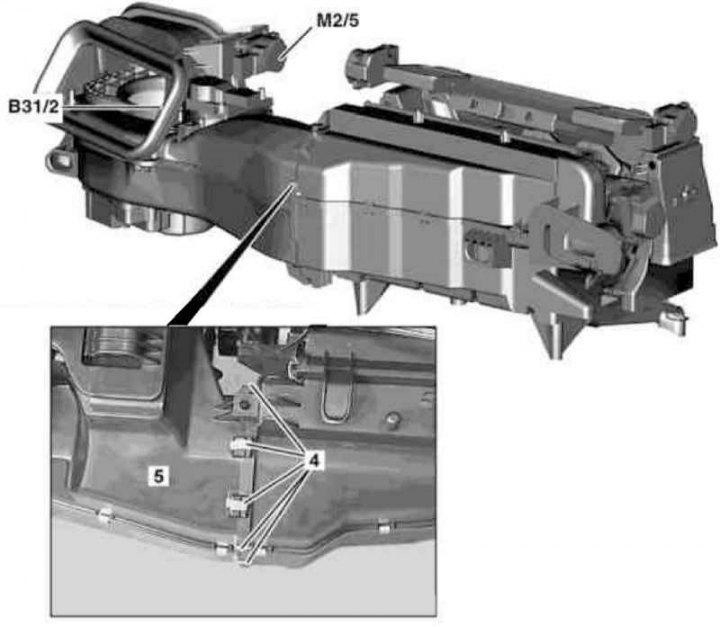
A/C evaporator installation details (1 of 3)
4 - Spring clips
5 — a casing of the fan of a heater
B31/2 - Air humidity sensor
M2 / 5 - The electric motor for the drive of the damper for switching circulation modes
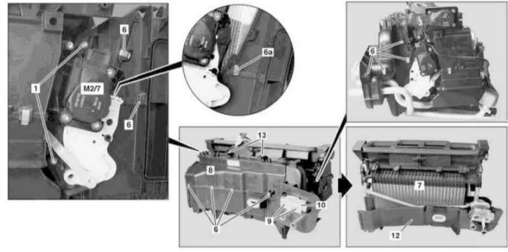
A/C evaporator installation details (2 of 3)
1 - Bolts; 6, 6a - Spring clips; 7 - Evaporator; 8 - Cover; 9 - Bolts; 10 - Expansion valve; 12 - Tray of the air distributor casing; 13 - Screws; M2 / 7 - Electric motor for driving the right mixing damper
A/C evaporator installation details (3 of 3)
14, 15 - Gaskets
16 - Guides
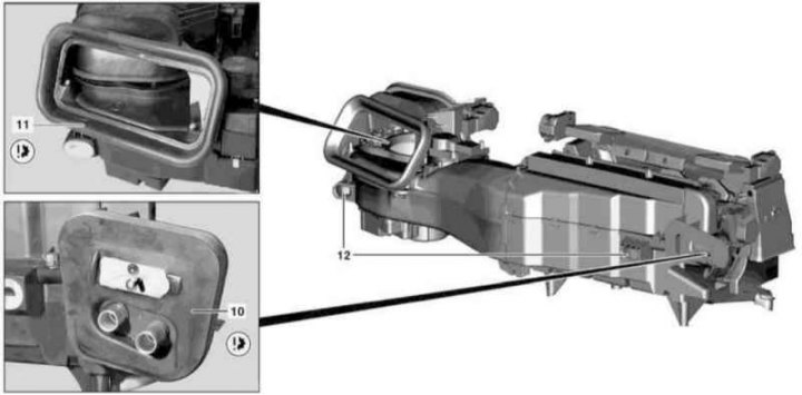
1. Remove the expansion valve (10) (see Section Removal and installation of the expansion valve).
2. Disconnect the wiring from the air humidity sensor (B31/2) and the electric motor of the damper drive for switching the air circulation modes (M2/5). Release and set aside the harnesses.
3. Remove 5 spring clips (4).
4. Remove the heater fan cover from the evaporator casing (5).
5. Turn out bolts (13 and 1) (TORX), remove 10 fasteners (6) and lower the evaporator (7) complete with lid (8), by pushing it forward and down.
6. Slightly pulling the electric motor to the side (M2/7) drive of the right mixing damper with the actuator, remove the clamps (6a).
7. Remove cover (8).
8. Remove the evaporator (7) from the casing.
9. Wipe the pan of the air distributor housing (12).
10. Install in reverse order - to lubricate the sealing elements (14 and 15) expansion valve and evaporator shell, use soapy water (Do not use any oils or greases!). Apply some lubricant to the guides (16). Make sure that the sealing elements and guides fit correctly.
11. Finally, synchronize the drive motors using the STAR DIAGNOSIS reader and clear the memory of the on-board self-diagnosis system (see chapter Engine Electrical Systems).