
Petrol models
Side supports
Support cushions
M112
Preparing to remove the pillows of the side supports of the suspension of the power unit (M112)
Installation details of the pillows of the side supports of the suspension of the power unit (M112)
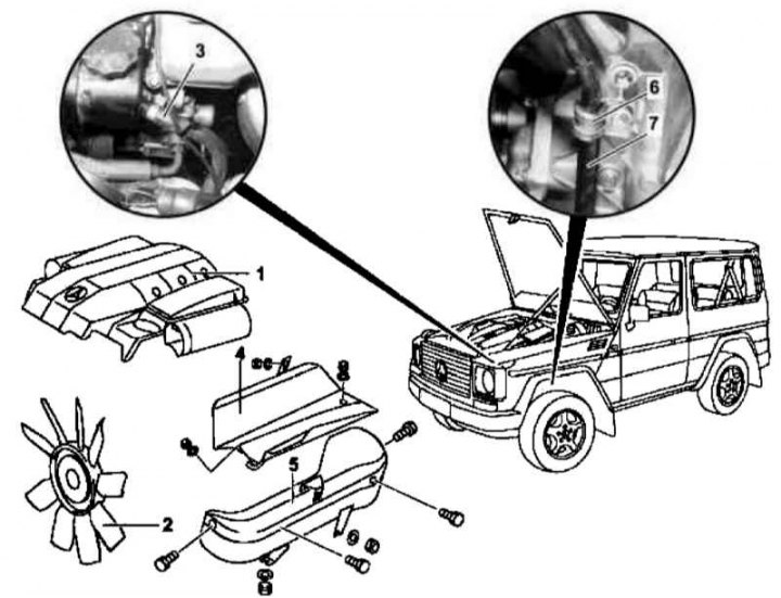
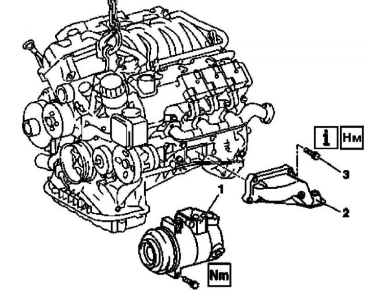
1. Disconnect the ground wire from the battery (see chapter Engine Electrical Systems).
2. Remove the air cleaner (1) (see chapter Power supply and exhaust systems).
3. Remove the viscous cooling fan assembly (2) (see chapter Refrigeration, heating, ventilation and air conditioning systems).
4. Disconnect the hydraulic return line from the steering pump (4), - immediately plug the open ends of the line and the nipple connector with plugs prepared in advance.
5. Unscrew the heat shields from the frame (4 and 5), - from the screen (5) release the electrical wiring of the left lambda probe.
Note. Don't try to split the screen (5) into two halves.
6. Turn out bolts (8).
7. Unscrew the support brackets (6) ATF lines (7) from the upper and lower sections of the oil pan.
8. Hang the power unit by both eyelets - make sure that no components (especially screens (4 and 5)) and communication lines were not pinched.
9. When dismantling the pillow of the right support, remove the heat shield (4), - if necessary, pull the power unit to the side.
10. Give fixing nuts and remove pillow assemblies (9) side supports of the suspension of the power unit.
Note. If the nuts are secured against turning, the cushions can be turned out of the support brackets.
11. Installation is carried out in the reverse order.
12. Finally, read the DTCs and clear the OBD memory using a handheld tester (HHT) /scanner STAR DIAGNOSIS (6511 1801 00) (see chapter Engine Electrical Systems).
M113
Preparing to remove the pillows of the side supports of the suspension of the power unit (M113)
Installation details of the pillows of the side supports of the suspension of the power unit (M113)
1. Disconnect the ground wire from the battery (see chapter Engine Electrical Systems).
2. Remove the air cleaner (1) (see chapter Power supply and exhaust systems).
3. Remove the viscous cooling fan assembly (2) (see chapter Refrigeration, heating, ventilation and air conditioning systems).
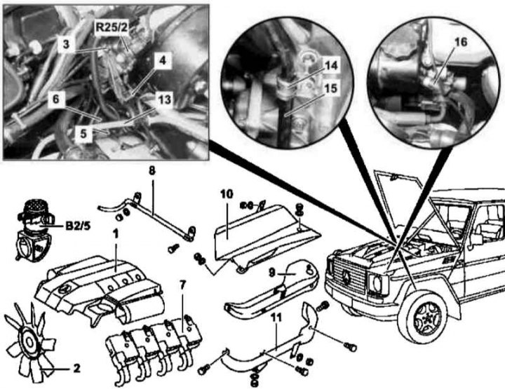
4. Disconnect the cable (3) throttle actuator from sensor (R25/2) provisions of the latter (TPS), then release the cable from the support bracket (4).
5. Release the Bowden cable (5) gas cable from the bushing (6).
6. Remove left ignition coils (7) (see chapter Engine Electrical Systems).
7. Remove mounting bracket (8).
8. Remove the top section (9) left thermal shield.
9. Unscrew the right heat shield from the frame (10) and bottom section (11) left screen - do not remove the screens from the frame.
10. Remove the hot-wire MAF sensor mounted in the intake air duct (B2/5) (see chapter Power supply and exhaust systems).
11. Disconnect the vacuum line (13) from the brake booster servo assembly at the rear of the intake manifold.
12. Remove the screws (17).
13. Unscrew the support bracket (14) ATF lines (15) from the lower and upper sections of the oil pan.
14. Disconnect the hydraulic return line from the steering pump (16), - immediately plug the open ends of the line and the nipple connector with plugs prepared in advance.
15. Hang the power unit by both eyes - make sure that no components (especially screens (10 and 11)) and communication lines were not pinched.
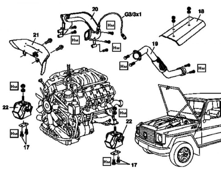
16. Loosen and remove the heat shield (18), then, - if the pillow of the right support is being dismantled, - remove the right screen (10), - if necessary, pull the power unit to the side.
17. Remove the left receiving section (19) exhaust systems (see chapter Power supply and exhaust systems).
Note. Mounting nuts must be replaced without fail.
18. Lower the unit - again make sure that no components are pinched.
19. Unbolt the connecting section (20) exhaust systems.
20. Loosen and remove the heat shield (21), - if necessary, pull the AT ventilation hose aside.
21. Disconnect the lambda probe wiring connector (G3/3x1)
22. Remove the connecting section (20) exhaust systems.
Note. Mounting nuts must be replaced without fail.
23. Hang the power unit by the front eye - make sure that no components are pinched.
24. Turn pillow inside out (22) appropriate support from its bracket - the fixing nuts must be fixed - and remove it from the engine.
25. Installation is carried out in the reverse order.
26. Finally, read the DTCs and clear the OBD memory using a handheld tester (HHT) /scanner STAR DIAGNOSIS (6511 1801 00) (see chapter Engine Electrical Systems).
Support brackets
Left support
Installation details of the bracket of the left side support of the suspension of the power unit (M112 and 113, using the example of M112)
1. Remove the side support pads (see above).
2. Remove the accessory drive belt (see Section Replacement of the auxiliary drive belt and elements of its tensioning mechanism).
3. Screw off the compressor (1) K / V and, without disconnecting the refrigeration lines, take it to the side and fix it in the engine compartment.
4. Unbolt the bracket (2) the left side support of the suspension of the power unit from the engine crankcase, - fixing bolts (3) must be replaced without fail.
5. Remove bracket (2).
6. Installation is carried out in the reverse order.
Right support
Installation details of the bracket of the right side support of the suspension of the power unit (M112 and 113, using the example of M112)
1. Remove the side support pads (see above).
2. Remove the shield (1) generator.
3. Turn out fixing bolts (3) and remove the bracket (2) right side support from the engine crankcase, - bolts (3) must be replaced without fail.
4. Installation is carried out in the reverse order - make sure that no communication lines are clamped between the bracket and the crankcase wall.
Rear support
Installation details of the rear suspension support of the power unit (all models)
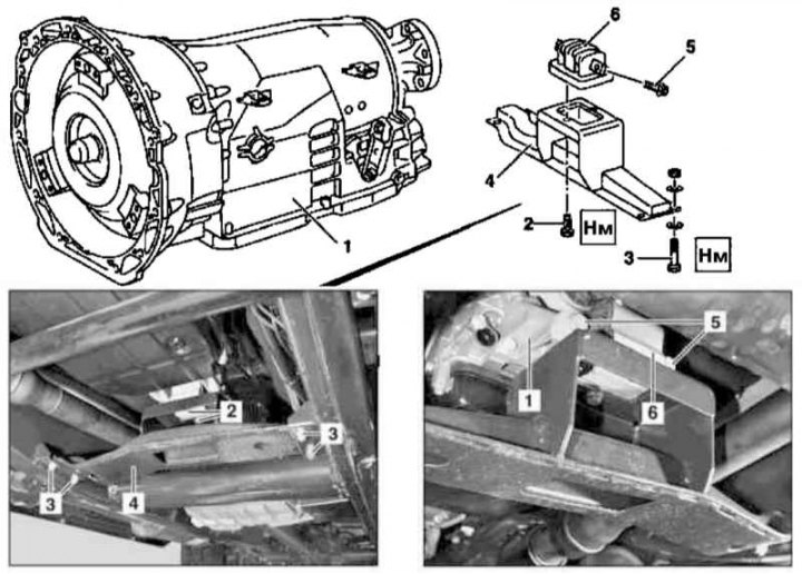
1. Jack up the car and put it on stands.
2. Support the transmission (1) suitable jack.
3. Turn out bolts (2).
4. Give self-locking bolt nuts (3), and remove the cross beam (4), - nuts must be replaced without fail.
5. Turn out bolts (5) and remove the rear support assembly (6) suspension of the power unit with beams (6).
6. Installation is carried out in the reverse order.
Diesel models
Side supports
Note. All self-locking fasteners must be replaced without fail.
Left support
M612
Installation details of the assembly of the left side suspension support of the power unit (M612)
1. Disconnect the ground wire from the battery (see chapter Engine Electrical Systems).
2. Appropriate models (code ET2) activate the service mode of the TELE AID emergency call system (see Section Activation / deactivation of the service mode of the TELE AID emergency call system).
3. Turn on the auxiliary battery and connect it to the standard battery, then disconnect the negative cable from the latter.
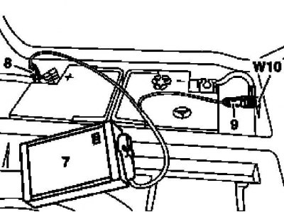
7 - Auxiliary battery
8 - Module positive wire terminal
9 - Terminal of the negative wire of the module
W10 - Battery Ground
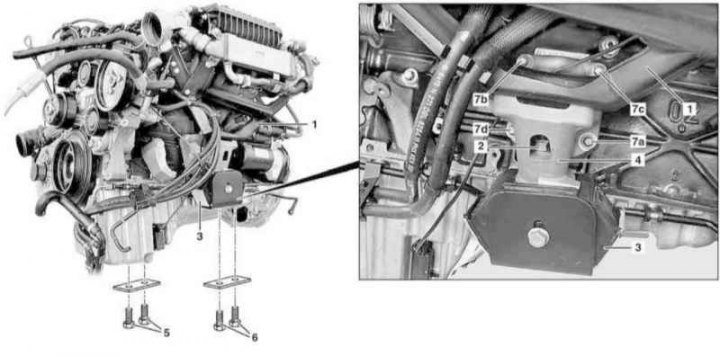
4. Jack up the car and put it on stands.
5. Remove the cylinder head cover trim panels (see illustration Details of the installation of trim panels for the cylinder head cover of the M612 engine).
6. Remove the air distributor (see chapter Power supply and exhaust systems).
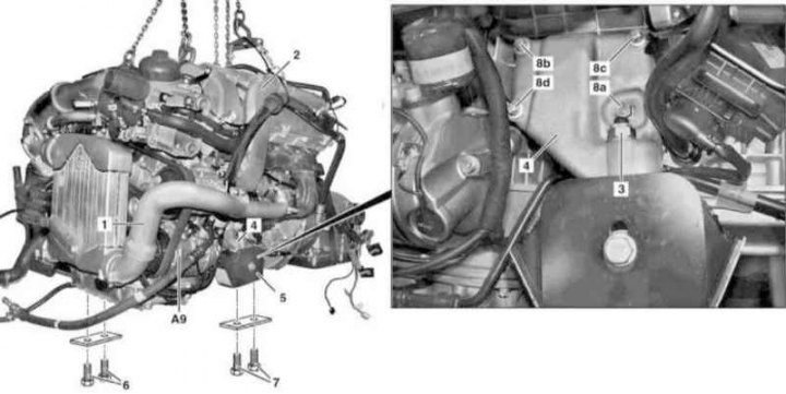
7. Remove mounting bracket (1) air distributor / bracket of the left side support of the suspension of the power unit.
8. Remove the air cleaner (see chapter Power supply and exhaust systems).
9. Remove primary catalytic converter (see chapter Power supply and exhaust systems).
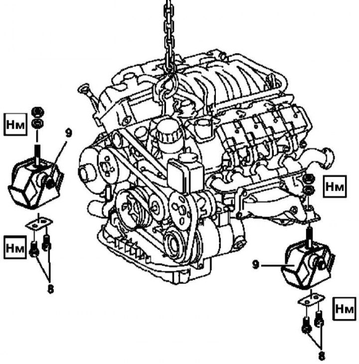
10. Give the nut (2) support cushion attachments (3) to bracket (4).
11. Connect the lifting rigging to both eyes of the power unit - make sure that no communication lines are pinched.
12. Turn out bolts (5 and 6) and separate the pillows (3) both side supports from the frame.
13. Release the rear support pad from your bracket (see below).
14. Hang the power unit assembly on the winch - make sure that no components are pinched.
15. Turn out bolts (7а-d) bracket mounting (4) left side support.
16. Remove the pillow (3) and bracket (4).
17. Installation is carried out in the reverse order.
Note. Bolt tightening (7а-d) should be done in alphabetical order: abcd).
18. Appropriate models (code ET2) deactivate the service mode of the TELE AID system (see Section Activation / deactivation of the service mode of the TELE AID emergency call system).
19. Finally, read the DTCs and clear the OBD memory using the STAR DIAGNOSIS scanner (6511 1801 00) (see chapter Engine Electrical Systems).
M628
Installation details of the assembly of the left side suspension support of the power unit (M628)
1. Follow the procedures of paragraphs 1, 4 and 8 (in the order listed) for M612.
2. Remove the hot-wire MAF sensor mounted in the left air intake pipe (B2/6) (see chapter Power supply and exhaust systems).
3. Disconnect the intake ducts on the mudguards of both wings.
4. Remove the crankcase protection.
5. Remove the cooling fan shroud (see chapter Refrigeration, heating, ventilation and air conditioning systems).
6. On models of the corresponding vehicle configuration (code H12) remove auxiliary heater (see chapter Refrigeration, heating, ventilation and air conditioning systems).
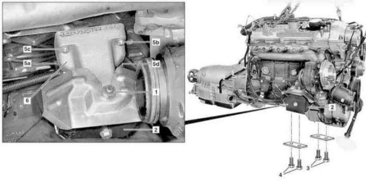
7. Remove the left lower sleeve (1) air path and left intake duct (2) (see chapter Power supply and exhaust systems).
8. Give the nut (3) pillow attachments (5) the left side support of the suspension of the power unit to its bracket (4).
9. Connect the lifting rigging to both eyes of the power unit - make sure that no communication lines are pinched.
10. Disconnect the exhaust system from the turbocharger (see chapter Power supply and exhaust systems).
11. Turn out bolts (6 and 7) and separate the pillows (5) side supports of the suspension of the power unit from the frame.
12. Release the rear support pad from your bracket (see below).
13. Hang the power unit assembly on the winch - make sure that no components are pinched.
14. Turn out bolts (8a-d) bracket mounting (4) left side support.
Note. bolt head (8a) has a hexagonal shape, other bolts (8b-d) equipped with TORX sockets.
15. Remove the pillow (5) and bracket (4).
16. Installation is carried out in the reverse order.
Note. Bolt tightening (8a-d) should be done in alphabetical order: abcd).
Right support
M612
Installation details of the assembly of the right side suspension support of the power unit (M612)
1. Follow the procedures in paragraphs 1 to 6 for the M612.
2. Remove primary catalytic converter (see chapter Power supply and exhaust systems).
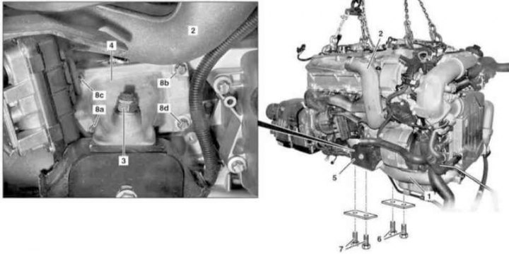
3. Give the nut (2) support cushion attachments (3) to bracket (4).
4. Connect the lifting rigging to both eyes of the power unit - make sure that no communication lines are pinched.
5. Remove the crankcase protection.
6. Connect the lifting rigging to both eyes of the power unit - make sure that no communication lines are pinched.
7. Turn out fixing bolts (3 and 4) and separate the cushions of both side supports from the frame.
8. Follow the procedures of paragraphs 13 and 14 for M612.
9. Turn out bolts (5а-d) bracket mounting (6) right side support.
10. Remove the pillow (2) and bracket (6).
11. Installation is carried out in the reverse order.
Note. Bolt tightening (5а-d) should be done in alphabetical order: abcd).
12. Appropriate models (code ET2) deactivate the service mode of the TELE AID system (see Section Activation / deactivation of the service mode of the TELE AID emergency call system).
13. Finally, read the DTCs and clear the OBD memory using the STAR DIAGNOSIS scanner (6511 1801 00) (see chapter Engine Electrical Systems).
M628
Installation details of the assembly of the right side suspension support of the power unit (M628)
1. Follow the procedures of paragraphs 1, 4 and 6 (in the order listed) for M612.
2. Remove the hot-wire MAF sensor mounted in the right air intake pipe (B2/7 (see chapter Power supply and exhaust systems).
3. Follow the procedures of paragraphs 4, 5 and 6 (in the order listed) for M628.
4. Remove the right lower sleeve (1) air path and right intake duct (2) (see chapter Power supply and exhaust systems).
5. Give the nut (3) pillow attachments (5) right side support of the suspension of the power unit to its bracket (4).
6. Then proceed in accordance with the instructions given in paragraphs 9 to 16 for the M628.
Rear support
1. The procedures for removing and installing the rear suspension support of the power unit are completely the same as those described above for gasoline models (see paragraphs 1 to 6 for petrol engines).