



Contents: V6 Engine ↡ Diesel engine 3.2 l ↡
Diagram of the chain drive of the gas distribution mechanism (timing) and the stages of the procedure for setting the valve timing phases. V6 engines
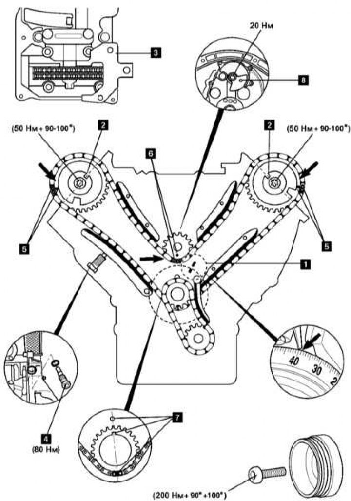
Diagram of the chain drive of the gas distribution mechanism (timing) and stages of the procedure for setting the valve timing phases (Diesel engine 3.2 l)
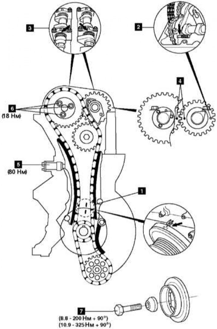
V6 Engine
Special tools:
- Cover for fixing the camshaft - No.112589054000.
- Camshaft locking key - No.112589000100.
- Wrench for camshaft sprocket bolt - No.112589010300.
- Left camshaft locking device - No.112589013200.
- Right camshaft locking tool - No.112589003200.
- Crankshaft pulley locking device - No.112589004000.
- Flywheel locking device - No.112589034000.
- Timing chain link separator kit - No.602589024000.
- Timing chain link separator (element 1) - No.602589023300.
- Timing chain link separator (element 2) - No.602589056300.
- Timing chain link separator (element 3) - No.602589056301.
- Chain link joining tool - No.602589003900.
- Set of dies for joining chain links - No.103589016300.
- Tool box - No.602589009800.
- Devices for fixing the chain on the camshaft sprockets - No.112589044000.
- Viscous coupling pulley holder - No.113589004000.
- Viscous coupling locking key - No.113589000100.
General precautions
1. Disconnect the negative cable from the battery.
2. Remove the spark plugs to make it easier to turn the engine.
3. Unless otherwise stated, turn the engine in the normal direction.
4. Familiarize yourself with the requirements for tightening forces of threaded connections.
5. If equipped, mark the position of the CKP sensor before removing it.
6. Do not turn the crankshaft using the camshaft drive sprockets or devices.
7. Do not turn the crankshaft and camshaft with the timing chain removed.
Valve timing installation procedures
1. Bring the piston of the first cylinder [1] to the position 40° after TDC.
2. Make sure that the parallel grooves of both camshafts are correctly aligned with the cylinder head cut [2].
3. Install the locking devices [3] on the camshafts.
4. On 112 engines, check that the alignment marks on the balance shaft [4] are correctly positioned.
5. Before performing repair procedures, remove the tensioner assembly [5].
Note: When the piston of the first cylinder is set to the 40° after TDC position, the camshafts can be rotated without the risk of the valves contacting the piston crowns.
6. When assembling, bring the piston of the first cylinder to the position 40° after TDC and ensure that the copper-plated links of the chain are aligned with:
- Timing marks of the sprockets of both camshafts [6];
- For 112 engines: with timing mark on balance shaft sprocket [7];
- With key and crankshaft timing mark [8].
Note: Once installation is complete, the copper plated chain links should be aligned every fourteenth turn.
Replacing the timing chain
1. Remove the right camshaft rocker arm shaft assembly with bearing caps.
2. Without tightening the fasteners, install the camshaft retaining cover [9] (special tool No.112589054000).
3. Install the chain locking devices on the camshaft sprockets (special tool No.112589044000).
4. Using the tools from the list above, connect the new chain to the old one on the right bank of cylinders - to put the chain on the sprockets, turn the crankshaft.
Note: The rocker arm axle assembly mounting bolts (M7x84 mm) cannot be reused and must be replaced.
Removal of the balance shaft on 112 engines is carried out in the following order:
- Insert a suitable locking rod into the counterweight on the rear shaft journal [11];
- Remove the mounting bolt and counterweight;
- Remove the balance shaft from the front side;
- During assembly, do not forget to lubricate the central bolt of the crankshaft pulley.
Note: Do not block the flywheel/drive plate when removing/installing the crankshaft pulley bolt.
Diesel engine 3.2 l
Special tools:
- Rod for fixing the camshaft - No.111589031500.
- Flywheel/Drive Disc Locking Tool (transmission dome) - № 601589024000.
- Flywheel/Drive Disc Fixing Tool Mounting Bolts (transmission dome) - M6x90 mm.
- Flywheel/Drive Disc Locking Tool (hole for installing starter) - № 602589004000.
- Timing chain link separator kit - No.602589024000.
- Timing chain link separator (element 1) - No.602589023300.
- Timing chain link separator (element 2) - No.602589046300.
- Timing chain link separator (element 3) - No.602589046301.
- Chain link joining tool - No.602589003900.
- Set of 1 dies for joining chain links - No.103589026300.
- Set of 2 dies for joining chain links - No.103589036300.
- Set of 3 dies for joining chain links - No.103589096300.
- Tool box - No.602589009800.
Article obtained from this portal (MercedesMAN)
General precautions
1. Disconnect the negative cable from the battery.
2. Remove the glow plugs to make it easier to turn the engine.
3. Unless otherwise stated, turn the engine in the normal direction.
4. Familiarize yourself with the requirements for tightening forces of threaded connections.
5. If equipped, mark the position of the CKP sensor before removing it.
7. Do not turn the crankshaft and camshaft with the timing chain removed.
8. After setting the valve timing, check the high-pressure fuel pump.
Valve timing installation procedures
Note: The timing chain can be replaced without removing the engine. Use the special tools from the list above. The new chain can be connected to the old one, put on the sprocket and then joined.
1. Bring the piston of the first cylinder [1] to the TDC position.
2. Insert the locking rod into the intake camshaft sprocket [2].
3. Make sure that the timing marks on the camshafts [3] and [4] are correctly aligned.
4. Before performing repair procedures, remove the tensioner assembly [5].
Note: The camshaft sprocket mounting bolts [6] cannot be reused and must be replaced with new ones.
5. After completing the repair work, install the tensioner [5].
Fastener tightening torque: 80 Nm.
Tightening torque of the crankshaft pulley bolt [7]:
- Bolt classification 8.8 200 Nm + 90°;
- Bolt classification 10.9 325 Nm + 90°.