
Lower protection of the engine compartment
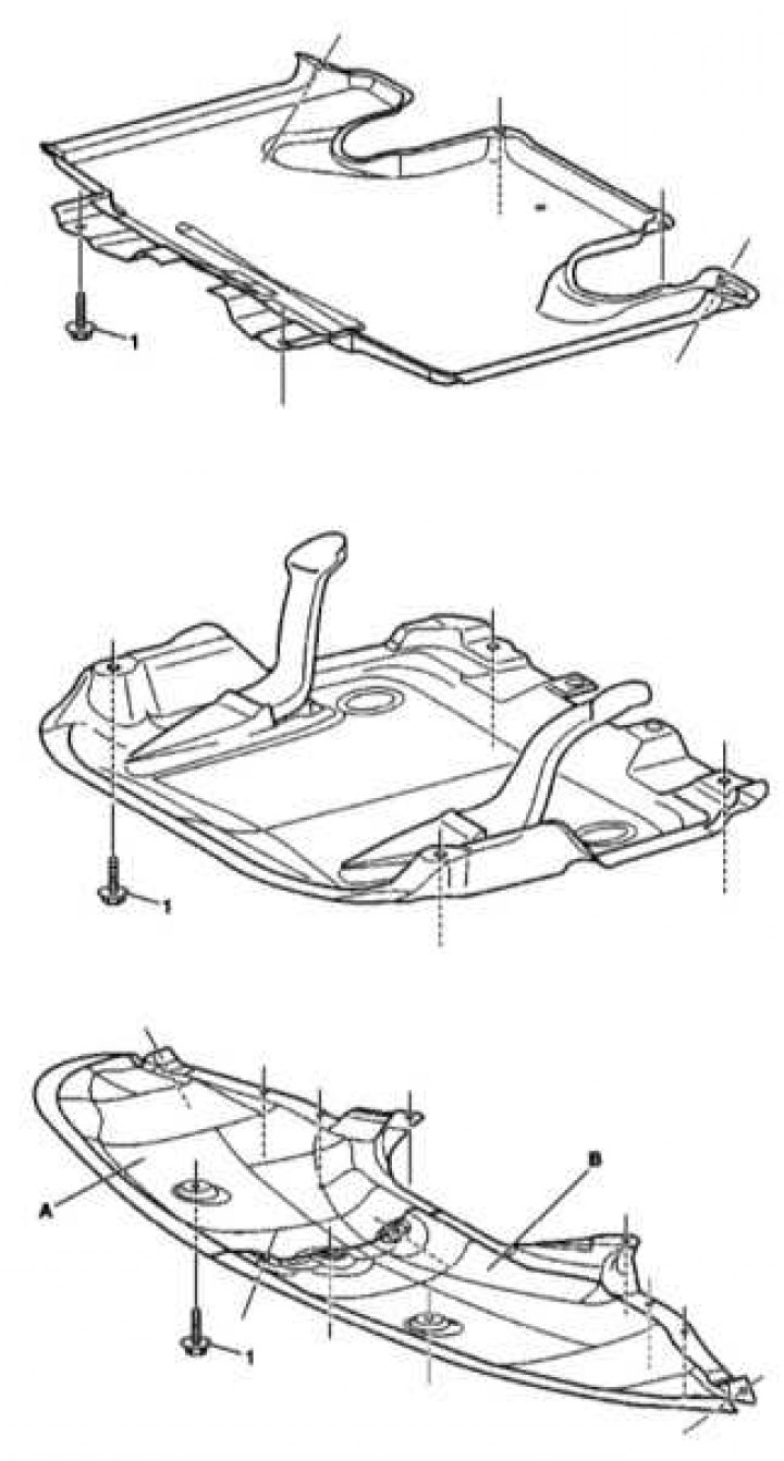
Rear of the engine compartment
1 - Bolt
The central part of the engine compartment
1 - Bolt
Front of the engine compartment
1 - Bolt
A - Right front trim
B - Left front trim
Elements of engines 112 and 113
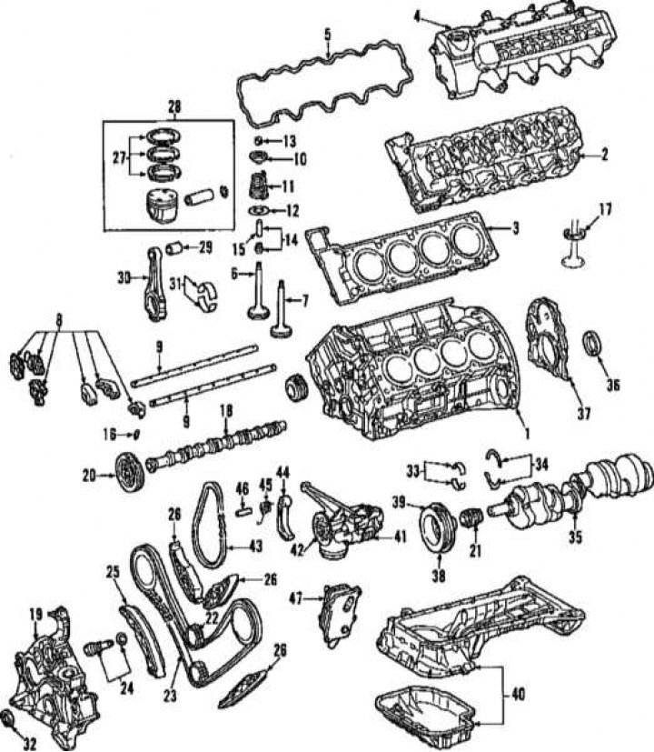
1 - Cylinder block; 2 - Cylinder heads; 3 - Gaskets of cylinder heads; 4 - Block head covers; 5 - Gaskets for head covers; 6 - Inlet valves; 7 - Exhaust valves; 8 - Valve levers; 9 - Axes of valve levers; 10 - Upper seat of the valve spring; 11 - Valve spring; 12 - Lower seat of the valve spring; 13 - Valve crackers; 14 - Oil caps; 15 - Auxiliary tube for planting the oil cap; 16 - Valve lifters; 17 - Valve seat; 18 - Camshaft; 19 - Front timing cover; 20 - Camshaft sprocket; 21 - Crankshaft sprocket; 22 - Intermediate gear; 23 - Timing chain; 24 - Tensioner; 25 - Chain tensioner shoe; 26 - Chain guides; 27 - Piston rings; 28 - Piston; 29 - Connecting rod pin bushing; 30 - Connecting rod; 31 - Inserts of connecting rod bearings; 32 - Front crankshaft oil seal; 33 - Bearing shells; 34 - Thrust half rings; 35 - Crankshaft; 36 - Rear crankshaft oil seal; 37 - Cover with rear crankshaft oil seal; 38 - Vibration damper; 39 - Crankshaft pulley; 40 - Oil pan; 41 - Oil pump; 42 - Oil pump sprocket; 43 - Oil pump drive chain; 44 - Tensioner lever; 45 - Tensioner spring; 46 - Finger; 47 - Oil cooler
Elements of the inlet pipeline
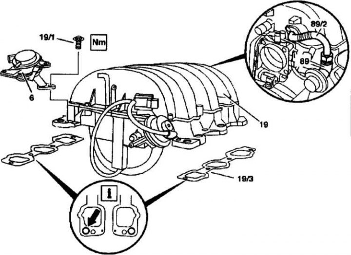
19 - Inlet pipeline; 19/1 - Bolt; 19/3 - Gasket; 89 - EGR valve; 89/2 - EGR valve tube; 6 - Combined valve; The arrow indicates the hole for the combination valve
Variable geometry intake airflow 12
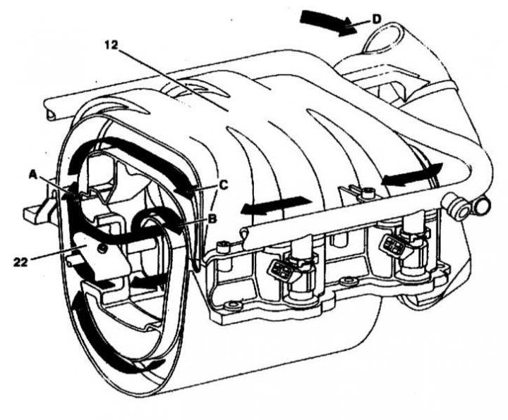
22 - Control damper; A - Air intake with the damper open; B - Air intake with the damper closed; C - To the engine; D - Air from the air filter
Intake and exhaust control on 112 and 113 petrol engines
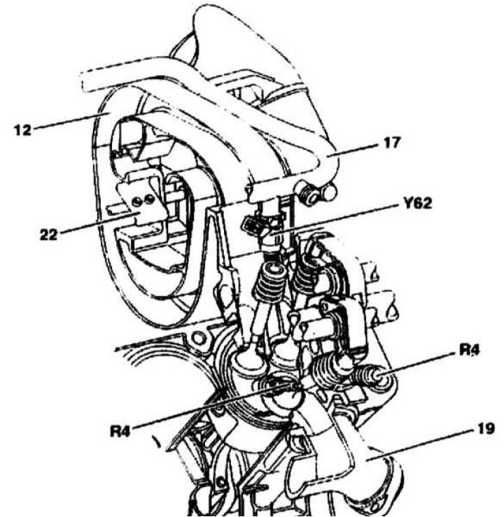
12 - Inlet pipeline; 17 - Fuel line; 19 - Exhaust manifold; 22 - Resonant damper; R4 - Spark plugs (double sparking); Y62 - Injector
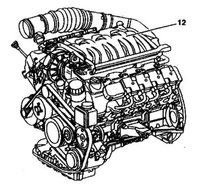
General view of the engine 113, equipped with an intake manifold 12 with variable geometry on (S430 and S500)
The bottom protection and the main elements of engines 112 and 113 are shown in the illustrations.
The gas distribution mechanism of gasoline engines is shown in the illustration. 3 valves applied (2 intake and 1 exhaust) and 2 spark plugs per cylinder. A special device allows you to disable valve control to reduce fuel consumption (refer to chapter Power and exhaust systems). The resonant intake pipe changes its length for each cylinder individually by means of electronically controlled flaps with servomotors.