
Disassembly
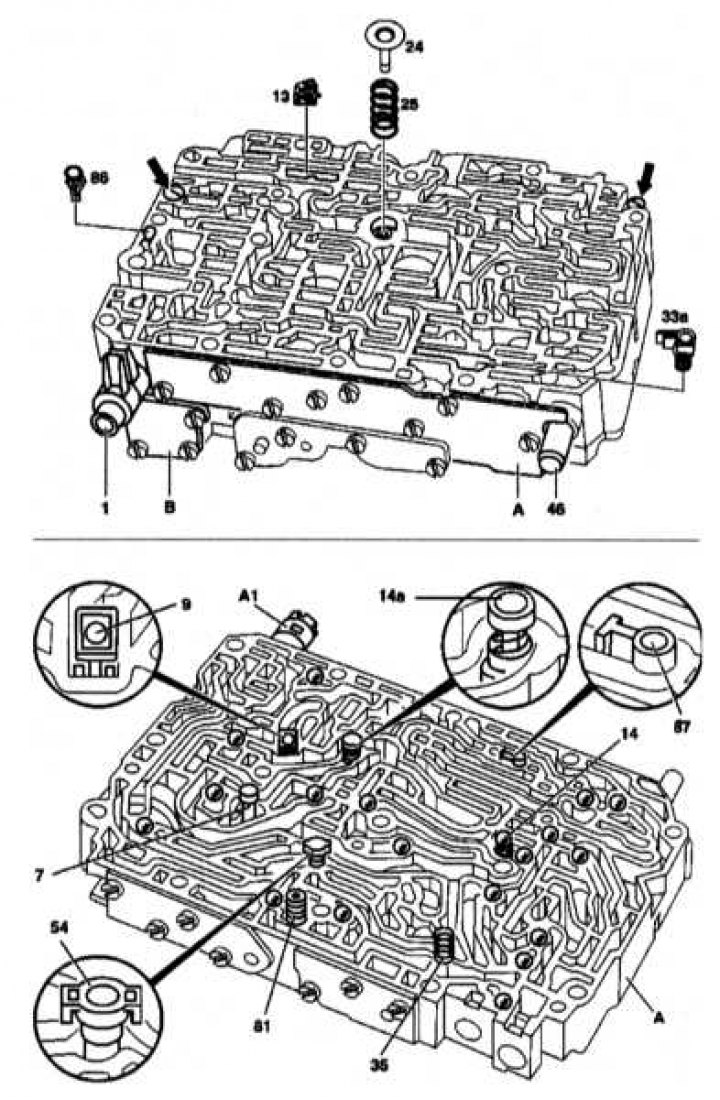
AT valve assembly design
1 - Gearshift valve; 7 - Blocking valve K1; 9 - Bypass valve without hole (white); 13 - Reed check valve with a hole; 14 - Balls; 14a - Pressure valve; 24 - Return valve of the secondary pump; 33a - Screen changeover valve B2; 35 - Spring; 46 - Pressure control valve; 54 - Bypass valve; 81 - Filter; 86 - Drain valve LB3; 87 - Throttle valve K2; A - Valve body; A1 - Gearshift valve; B - Damper housing
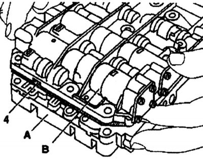
Removing the damper housing (IN) with intermediate plate
4 - Intermediate plate; A - Valve body; B - Damper housing
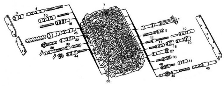
AT valve assembly design
1 - Gearshift valve; 3 - Piston of the control valve 2-3; 4 - Control valve 2-3; 5 - Adjusting valve for adaptability of the rotation converter; 7 - Blocking valve K1; 10 - Switching valve B1; 11 - Piston of the control valve 3-4; 12 - Control valve 3-4; 16 - Main pressure control valve; 17 - Control valve 1-2; 18 - Control valve bushings 1-2; 19 - Piston of the control valve 1-2; 26 - Adjusting valve for working pressure; 27 - Cork; 32 - Pressure control valve at full throttle opening; 33 - Switching valve B2; 35 - Lubrication pressure switching finger; 38 - Control valve B1; 39 - Piston of the control valve 81; 40 - Downshift valve (kick-down); 41 - Pressure regulator switching valve; 44 - Vacuum pressure regulator valve; 45 - Pressure regulator control valve; 46 - Piston control valve pressure regulator
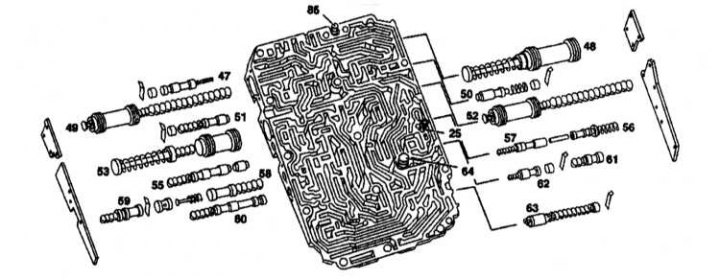
AT valve assembly design
25 - Pressure reducing valve; 47 - Switching pressure control valve; 48 - Damper K1; 49 - Damper K2; 50 - Adjusting damper valve K1; 51 - Adjusting damper valve K2; 52 - Damper B1; 53 - Switching damper; 55 - Blocking valve DV2; 56 - Switching valve during engine braking; 57 - Control valve B1; 58 - Adjusting valve of the including damper; 59 - Switching valve K2; 60 - Safety valve B2; 61 - Locking valve of the shift brake; 62 - Blocking valve RV1; 63 - Downshift damper (kick-down); 64 - Grease pressure control valve; 85 - Pressure limiting valve
1. Turn away bolts.
2. Remove valves (13), (24), (86) and screen (33a).
3. Fix the valve body (A) and damper housing (IN) together and turn them over.
4. Carefully lift the damper housing (IN) with intermediate plate.
5. Remove all 19 balls (14).
6. Remove valves, filter and switch fingers.
7. Unscrew the side cover from the valve body.
8. Adjust the pressure at full throttle.
Assembly
Assembly is carried out in the reverse order of disassembly. Tighten the mounting bolts (arrows) so that both parts of the body cannot move relative to each other.