
Section 1
Disassembly
Transmission Component Installation Details (section 1)
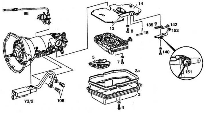
3 - Crankcase AT; 3a - Gasket; 4, 7, 8, 108, 140 - Bolts; 5 - Oil filter; 13 - Bottom cover; 14 - Large intermediate plate; 15 - Guide oil pipe; 98 - Gearshift cable; 135 - Locking pin; 142 - Retaining spring; 151 - Adjusting spring and locking gasket; 152 - Locking lever; Y3/2 - Solenoid valve
1. Remove the gearbox from the rotation converter.
2. Remove shift cable (98) with vacuum drive.
3. Remove the solenoid valve (Y3/2).
4. Disconnect a transmission from arms.
5. Remove the valve body (9).
6. Remove the bottom cover (13) with intermediate plate (14).
7. Remove the single port valves, B2 brake band, oil slinger and temperature flap from the gearbox housing.
Assembly
Assembly is carried out in the reverse order of disassembly.
Section 2
Disassembly
Transmission Component Installation Details (section 2)
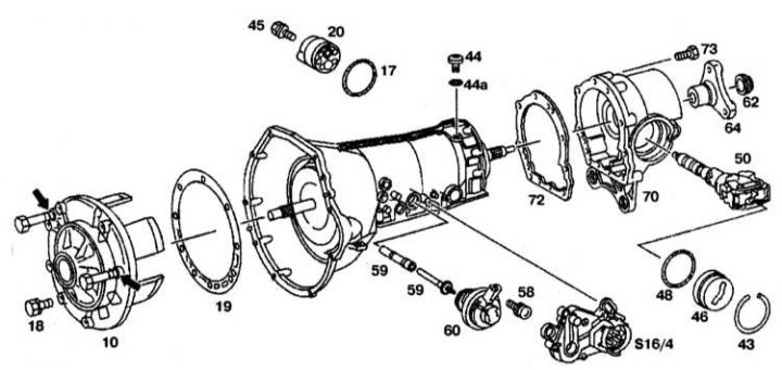
10 - Front cover with secondary pump; 17, 44a, 48 - O-rings; 18, 45, 58, 73 - Bolts; 19, 72 - Gaskets; 20 - Secondary pump; 43 - Retaining ring; 44 - Vent plug; 46 - Cover; 50 - Centrifugal regulator; 59 - Pressure modulator valve; 59a - Finger; 60 - Pressure modulator; 62 - Nut; 4 - Flange; 70 - Rear cover of the gearbox; S16/4 - Starter lock switch
1. Disassemble the gearbox.
2. Remove the modulator (60).
3. Remove the starter interlock switch (S16/4).
4. Remove secondary pump (see Section Removal, maintenance and installation of the secondary pump (AT up to No. 3652931)).
5. Remove the vent plug (44) and sealing ring (44a).
6. Remove the transmission front cover (10) with secondary pump (20).
7. Remove flange (64).
8. Disconnect the retaining ring (43), cover (46) and sealing ring (48).
9. Remove the rear gearbox cover (70).
Assembly
Assembly is carried out in the reverse order of disassembly.
Section 3
Disassembly
Transmission Component Installation Details (section 3)
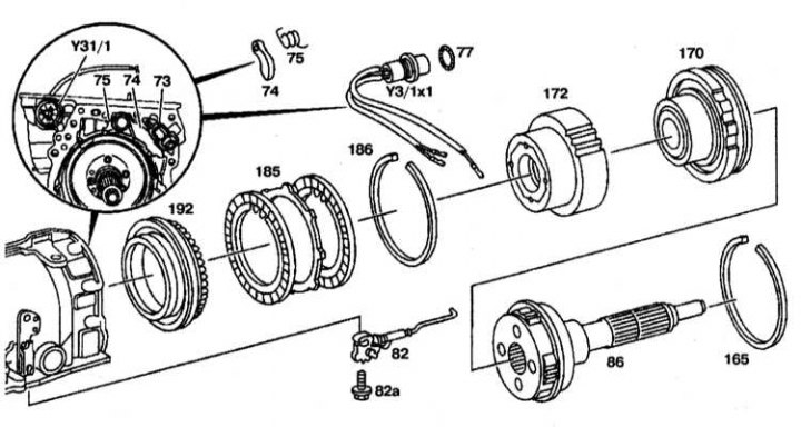
73 - Plastic guide; 74 - Parking brake dog; 75 - Extension spring; 77 - O-ring; 82 - Locking plate with rod; 82a - Bolt; 36 - Output shaft; 165, 188 - Retaining ring; 170 - Crown gear; 172 - Overdrive clutch support plate; 192 - Overdrive clutch piston; Y3/1x1 - Cork
1. Disassemble the gearbox (see sections 1 and 2).
2. Remove the extension spring (75) and unhook the parking brake pawl (74).
3. Remove the plastic guide (73).
4. Remove the lock plate (82) with traction, unscrewing the bolt (82a).
5. Remove the cork (Y3/1x1) solenoid valves and O-ring (77) from the gearbox housing.
6. Remove the overdrive brake and clutch.
Assembly
Assembly is carried out in the reverse order of disassembly.
Section 4
Disassembly
Transmission Component Installation Details (section 4)
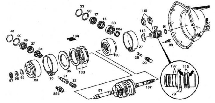
15 - Brake piston B2; 17 - Brake piston cover B2; 23, 41 - Retaining rings; 27 - Brake band of brake B2; 28 - Finger; 29 - B2 brake bearing; 30 - Brake band B1; 31 - Brake bearing B1; 33, 60 - Bolts; 34 - Brake guide B1; 37 - Brake piston B1; 40 - Brake piston cover B1; 79 - Support flange; 83 - Clutch K1; 85 - LB3 brake disc spring ring; 87 - Planetary pair; 88 - Radial oil seal; 88a - Plastic brake guide ring B2; 90, 91, 197 - O-rings; 95, 96 - Gaskets; 97 - Thrust bearing; 100 - Clutch K2; 113 - Support pad; 115 - Teflon rings; 133 - Multi-disc brake B3; 134 - Damper spring; 167 - Output shaft; 565 - AT overload protection sensor
1. Disassemble the gearbox (see sections 1, 2 and 3).
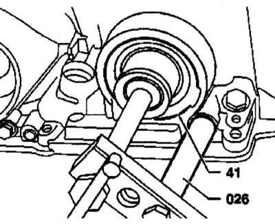
2. Remove brake bearing B1 (31) them housing by unscrewing the bolt (33) or AT overload protection valve (S65). 3. Attach puller (026) and screw it onto the gearbox. Attach the puller (026). Remove retaining ring (41).
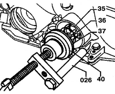
4. Loosen the puller (026). Remove piston with brake pin B1 (37) together with lid (40) and return springs (35) And (36).
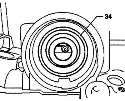
5. Remove the B1 brake band guide (34). Replace the O-ring in the gearbox housing.
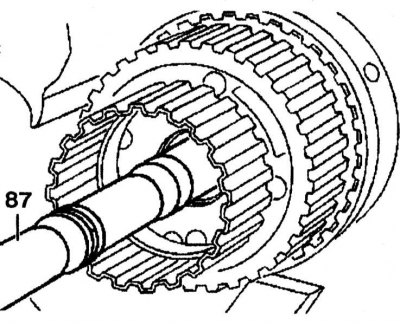
6. Remove clutch K1 (83) with brake band brake B1 (30). Remove the multi-disc brake B3 (arrow). Carefully remove the drive shaft (87).

7. Remove damper spring (134) from the gearbox housing.
8. Remove brake piston B2 (15), by pressing the brake cover B2 (17), by removing the retaining ring (23).
9. Remove the plastic ring (88a) and radial seal (88).
10. Remove clutch K2 (100).
11. Remove the B2 brake band (27).
12. Remove support ring (113) from the flange (79).
13. Remove the retaining flange (79) from the gearbox housing by unscrewing the bolts (80).
Assembly
1. Install the flange (79) with sealing ring (197) and teflon rings (115) into the gearbox housing. Before installing the flange (79), make sure the lubricating constrictor is installed in the flange (79), - to install the flange (79) use two bolts approximately 80 mm long.
2. Install the support pad (113) on the flange (79).
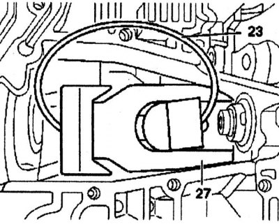
3. Insert brake bearing B2 (29) with a finger (20) into the gearbox housing. Larger finger diameter (28) must point towards the brake band B2 (27).
4. Insert the plastic guide ring (88a) and radial seal (88) into the gearbox housing. When installing, the sealing lip must point towards the piston cover (17) brake band.
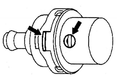
5. Check the thrust part of the brake B2 (29) for curvature. Thrust, hole and eye (arrows), when removed, should be located in the same position.
6. Install a new o-ring in the gearbox housing. Insert brake stop B2 (29) ear up.
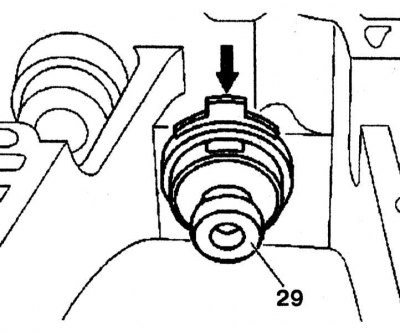
7. Compress brake band B2 (27) as far as possible and insert it into the body - the brake band can be installed using the retaining ring for piston B2 (23).
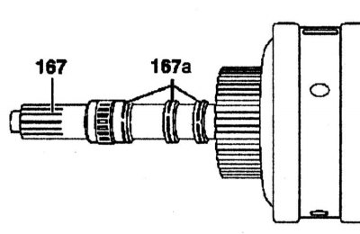
8. Lubricate the grooves on the output shaft (167) and insert teflon rings (167a).
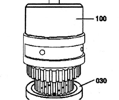
9. Install clutch K2 (100) to the planetary pair using the device (030).
10. Insert the planetary pair into the gearbox housing by turning the drive shaft (87).
11. Install the gearbox with the driven shaft (87) vertically up.
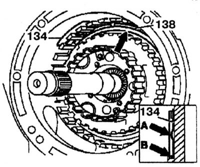
12. Check the installation of the planetary pair. The planetary pair is correctly installed when the upper edge of the coupling base (arrow) lower than the base (138) external multi-disc brake LB3. Install the spring (134). ledge (arrow A) on the spring must be installed inward. The damper spring must be installed in the groove (arrow B) in the gearbox housing.
13. Install brake piston B2 (15), by pressing the brake piston cap B2 (17) and inserting the retaining ring (23).
14. Install and check the clearance in the LB3 multi-disc brake.
15. Install clutch K1 (83) for a planetary pair (87).
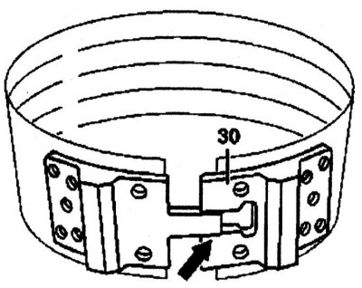
16. Install brake band B1 (30).
17. Check the clearance of the brake band of brake B1 (see Section Brake clearance measurement B1) - the nominal value is 1.8-2.4 mm.
18. Check the gap in the brake band of brake B2, - the nominal value is 5.5-6.0 mm.
19. Check clearance in multi-disc brake B3 (see Section Setting and checking clearance in multi-disc brake B3) - the nominal value is 1.5-2.0 mm.
20. Further assembly is carried out in the reverse order of removal.