
Petrol models
All petrol models must use unleaded petrol only. The engine management system operates in such a way as to get the most out of the engine while minimizing fuel consumption and exhaust emissions. The vapor recovery system prevents fuel vapor from entering the atmosphere from the fuel tank. An exhaust gas recirculation system was installed.
Functional diagrams of systems for reducing the toxicity of exhaust gases (as part of the engine management system)
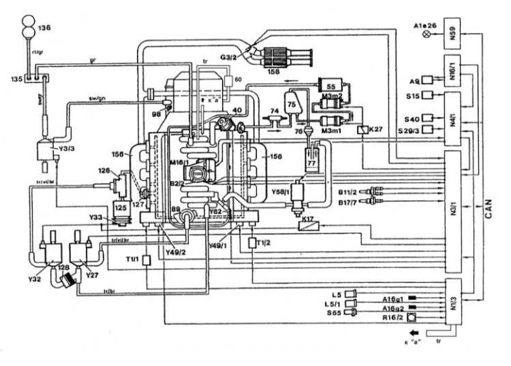
Functional diagram of the injection system for engines 119 and 104 (engine shown 119)
40 - Diaphragm pressure regulator; 55 - Fuel filter; 60 - Vacuum device; 74 - Fuel cooler; 75 - Fuel tank; 76 - Ventilation valve; 77 - Carbon adsorber for gasoline vapors; 89 - EGR valve (left on engine 120); 89a - Right EGR valve on the 120 engine; 98 - Damper pneumatic upshift device; 125 - Air pump; 126 - Shut-off valve for mixing air into the exhaust manifold; 127 - Check valve for mixing air into the exhaust manifold (left on engine 120); 127a - Check valve for mixing air into the right, on engine 120, exhaust manifold; 128 - Check valve (underpressure); 135 - Check valve (vacuum creation); 136 - Vacuum chamber; 156 - Exhaust manifold; 158 - Catalytic converter; A1e26 - Failure warning lamp (MIL/» Check engine»); A9 - A/C compressor; A16 - Knock sensors (KS); A16g1 - Left knock sensor KS; A16g2 - Right knock sensor KS; B2/2, B2/3 - Thermometric air mass sensor (MAF); B11/2 - 4-pin coolant temperature sensor (ECT); B11/7 - Intake air temperature sensor (IAT); B11/9 - Left ECT sensor; B17 / 5 - Left IAT sensor on engine 120; B17/6 - Right IAT sensor on engine 120; B17/7 - Intake air temperature sensor (IAT); G3/2 - Heated lambda probe (left on engine 120); G3 / 4 - Right heated lambda probe on engine 120; K17 - Relay for the air mixing system in the exhaust manifold; K27 - Fuel pump relay; K27 / 1 - Left relay for fuel pumps 1 and 2 on engine 120; K27 / 2 - Right relay for fuel pumps 1 and 2 on engine 120; L5 - Crankshaft position sensor (CKP); L5 / 1 - Camshaft position sensor (CMP); L5 / 2 - Left CMP sensor on engine 120; L5 / 3 - Right CMP sensor on engine 120; L5 / 4 - Left CKP sensor on engine 120; L5 / 5 - Right CKP sensor on engine 120; M3m1 - Fuel pump 1; M3m2 - Fuel pump 2; M16/1 - Acceleration actuator (throttle actuator); M16 / 3 - Left throttle actuator on engine 120; M16/4 - Right throttle actuator on engine 120; N1/3 - EZL/AKR ignition system control unit; N1 / 4 - Left control unit of the ignition system on the engine 120; N1 / 5 - The right control unit of the ignition system on the engine 120; N3/1 - ECM; N3/2 - Left ECM on engine 120; N3/3 - Right ECM on engine 120; N4/1 - Acceleration control unit (throttle actuator); N4 / 3 - Control unit for the idle speed stabilization system (IAC) /tempostat; N16/1 - Voltage stabilizer; N59 - Diagnostic module (california models)
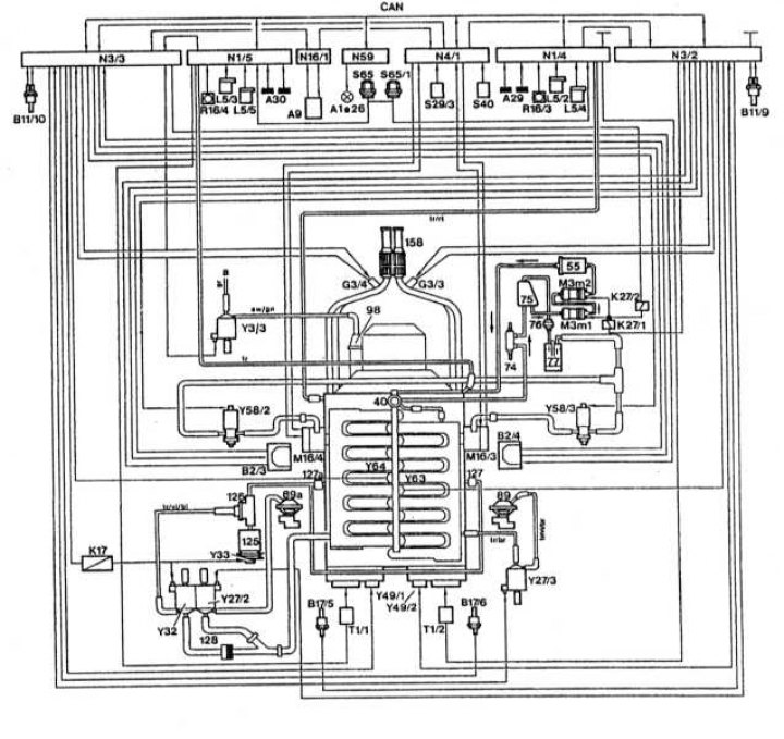
Functional diagram of the injection system of the engine 120
R16 / 2 - Exemplary resistor of the ignition module; R16 / 3 - Exemplary resistor of the left ignition module on the engine 120; R16 / 4 - Exemplary resistor of the right ignition module on the engine 120; S29 / 3 - Limit switch idling; S40 - Tempostat switch; A - Off; B - Overclocking / installation; SP - Reinstall; V - Engine braking / installation; S65 - Transmission overload safety switch (band brake B1); S65/1 - Transmission overload safety switch (band brake B21) . Engine 120; T1 - Ignition coil; T1 / 1 - Ignition coil of the right cylinder head on the engine 120; T1 / 2 - Ignition coil of the left cylinder head on the engine 120; Y3/3 - Pneumatic valve for upshift damper; Y27 - EGR switching valve; Y27 / 2 - Left EGR switch on engine 120; Y27 / 3 - Right EGR switch on engine 120; Y32 - Switching valve for the air mixing pump in the exhaust manifold; Y33 - Electromagnetic clutch of the pump for mixing air into the exhaust manifold; Y49 - Solenoid valve for camshaft adjuster; Y49 / 1 - Solenoid valve for the camshaft regulator of the left cylinder head on the engine 120; Y49 / 2 - Solenoid valve for the camshaft adjuster of the right cylinder head on the engine 120; Y58/1 - Pneumatic switch for carbon adsorber; Y58 / 2 - Left pneumoswitch of the coal adsorber on the engine 120; Y58 / 3 - Right pneumoswitch of the coal adsorber on the engine 120; Y62 - Fuel injectors (left row of cylinders on the engine 120); Y63 - Fuel injectors of the right row of cylinders on the engine 120
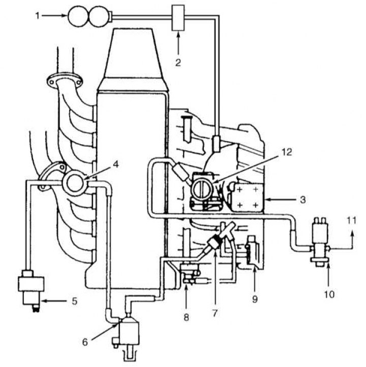
Diagram of laying vacuum lines (engines 104)
1 - Vacuum receiver; 2 - Vacuum distributor; 3 - Resonant damper; 4 - Air cut-off valve (with built-in control valve); 5 - Electric vacuum pump; 6 - Air pump switch valve; 7 - Vacuum control valve; 8 - Diaphragm pressure regulator; 9 - Absolute pressure sensor in the intake manifold (MAP); 10 - Purge control valve; 11 - To the coal adsorber; 12 - Throttle actuator
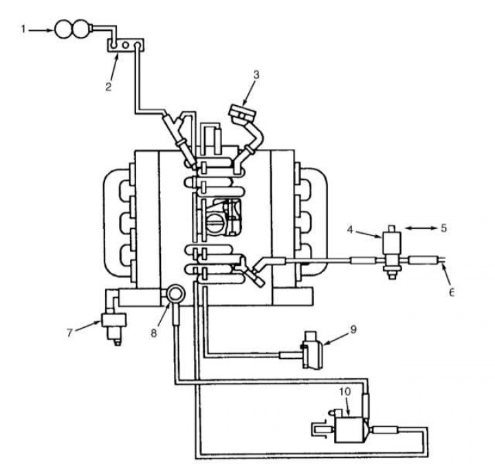
Diagram of laying vacuum lines (engines 119)
1 - Vacuum receiver; 2 - Control valve for vacuum supply; 3 - Diaphragm pressure regulator; 4 - Purge control valve; 5 - To the control module of the ME-SFI injection system; 6 - To the coal adsorber; 7 - Electric air pump; 8 - Valve for shutting off the air supply; 9 - Absolute pressure sensor in the intake manifold (MAP); 10 - Air pump switch valve
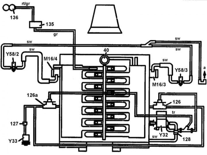
Scheme of connecting vacuum and evaporation lines to the inlet pipeline (engines 120)
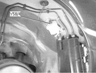
40 - Diaphragm pressure regulator; 125 - Air pump; 126 - Air cut-off valve; 126a - Right air shut-off valve; 127 - Left control valve (air mixing); 128 - Vacuum control valve; 135 - Control valve of the vacuum supply line; 136 - Vacuum receiver; M16 / 3 - Left activator of the electronic accelerator / tempostat / idle speed control device. On the left side of the power unit; M16 / 4 - Right activator of the electronic accelerator / tempostat / idle speed control device. On the right side of the power unit; Y32 - Air pump switch valve; Y33 - Air pump electromagnetic clutch; Y58/2 - Left purge control valve; Y58/3 - Right purge control valve; a - to the coal adsorber; rt - red; gr - grey; sw - black; tr - neutral
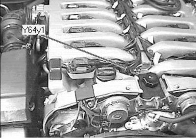
The injector of the first cylinder is located in the right front of the power unit (on the example of a 12-cylinder engine)
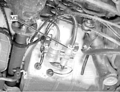
The fuel pump assembly is placed under the vehicle, in front of the right rear axle shaft
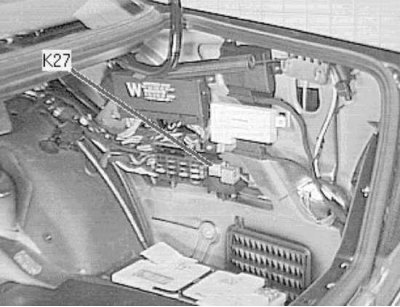
The fuel pump relay is located on the right side of the luggage compartment, behind the rear fuse box
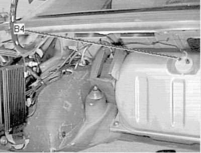
The fuel gauge is located in the left front corner of the luggage compartment, on the fuel tank
The intake manifold changeover valve is placed under the intake manifold (bottom view)
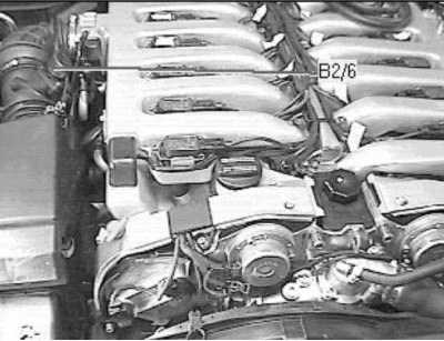
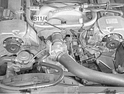
Left thermometric air mass meter (MAF) placed on the right side of the engine compartment, on the air intake sleeve
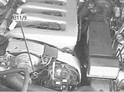
The left coolant temperature sensor is located on the left front of the power unit
The right coolant temperature sensor is located on the left front of the power unit
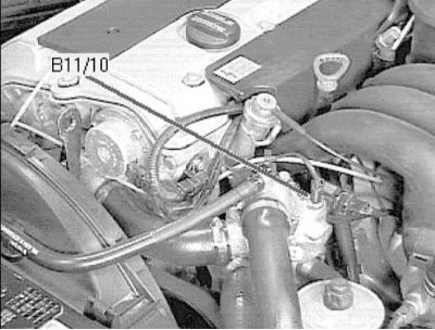
coolant temperature sensor (ECT) located at the top of the left front corner of the power unit
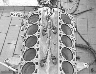
Left knock sensor (KS) located in a recess on top of the engine (The picture shows the engine removed from the car)
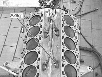
Left knock sensor (KS) 1 is located in a recess on top of the engine (The picture shows the engine removed from the car)
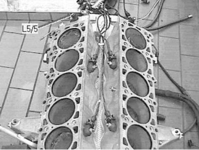
Right crankshaft position sensor (CKP) on the V12 engine, - at the rear at the top of the cylinder block (engine removed from car)
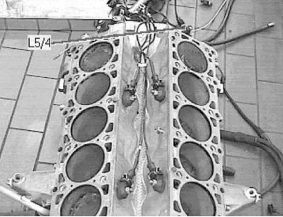
Left Crankshaft Position Sensor (CKP) on the V12 engine, - on the right on the rear wall of the engine block (The picture shows the engine removed from the car)
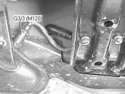
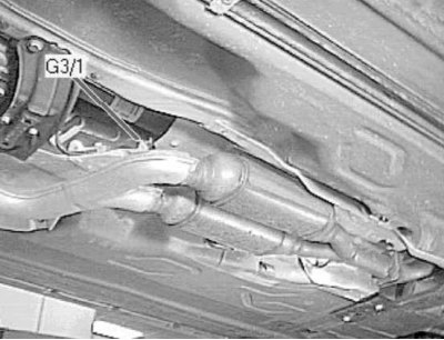
Left pre-catalytic lambda probe 1, - under the car, close to the DP, above the catalytic converter
Pre-catalytic lambda probe 1, - under the car, close to the DP, on the tubular section of the exhaust system, in front of the catalytic converter
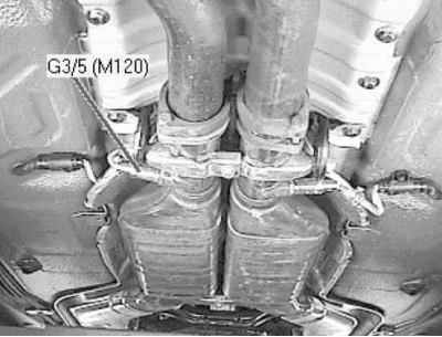
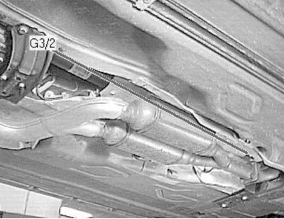
Left post-catalytic lambda probe 2, - under the car, near the DP
Post-catalytic lambda probe 2, - under the car, near the DP under the rear seat, in the exhaust system pipe behind the catalytic converter
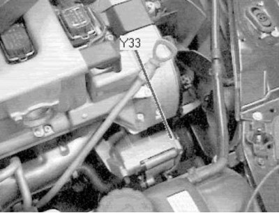
The electromagnetic clutch of the air mixing pump is located at the bottom in the right front corner of the engine compartment

The right canister purge valve is located on the left side of the engine compartment, on the wheel arch mudguard
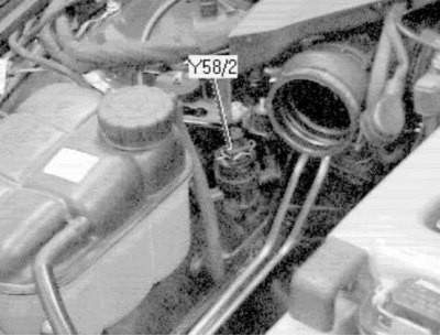
The left canister purge valve is located on the right side of the engine compartment, on the wheel arch mudguard, behind the expansion tank of the cooling system
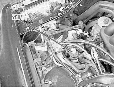
The canister purge valve is located in the left front corner of the engine compartment, on the wheel arch mudguard
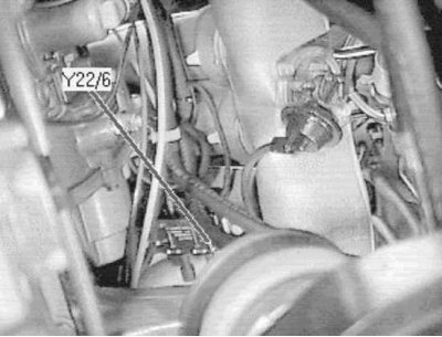
The canister purge shut-off valve is located under the car, at the rear of the left rear wheel arch
Crankcase ventilation system (PCV)
To eliminate leakage of unburned hydrocarbons into the atmosphere, the engine is completely sealed. Gases and oil vapors formed in the crankcase enter the intake manifold through a strainer and burn in the cylinders along with the fuel.
Gases are removed from the crankcase due to the pressure difference in the crankcase and inlet pipeline (pressure in the crankcase is higher).
Reducing the toxicity of exhaust gases
To reduce the amount of harmful emissions into the atmosphere on all gasoline models, a three-function catalytic converter is integrated into the exhaust system. The fuel injection control system has feedback, which includes an oxygen sensor. This sensor, installed in the exhaust system, constantly informs the control unit about the composition of the exhaust gases. Depending on the received data, the control unit corrects the quality of the mixture supplied to the combustion chambers and, thus, optimizes the combustion of the fuel.
A heating element is built into the lambda probe, which is switched on by the control unit through a special relay. The working surface of the lambda probe is sensitive to changes in the oxygen content in gases. Depending on the oxygen concentration, the sensor sends signals of different voltages. If the mixture is too rich - the oxygen content in the exhaust gases is very low, the sensor gives low voltage signals. The voltage increases as the mixture becomes leaner and the oxygen content of the gases increases. The converter works most efficiently with the optimal composition of the combustible mixture (14.7 parts of air to 1 part of fuel). At the optimum concentration of oxygen in the exhaust gases, a jump in voltage occurs on the sensor. This jump is the starting point for the control unit when adjusting the quality of the mixture.
There are two sensors installed. One - before, and the second - after the assembly of the catalytic converter. This achieves a more accurate monitoring of the composition of the exhaust gases.
Exhaust gas recirculation system (EGR)
The exhaust gas recirculation system helps to reduce the amount of NOx in the exhaust gases. To do this, a small part of the exhaust gases is fed into the intake manifold through a special valve. The valve of the recirculation system is controlled by the control unit.
Evaporative Emission System (EVAP)
Refer to Engine Control System Diagrams (Engine management system for 3.2L models, Engine management system for 4.2 and 5.0 l models).
To reduce the emission of unburned hydrocarbons into the atmosphere, a fuel vapor recovery system is installed on all gasoline models. The filler neck of the fuel tank is hermetically sealed with a lid, a carbon adsorber is installed under the fuel tank. It collects fuel vapors that form in the tank while the car is parked and is stored there until the filter purge begins at the signal of the control unit. Then fuel vapors begin to flow through the valve (s) purge into the intake manifold, where they are mixed with the working mixture and then burned in the usual way in the combustion chambers.
To ensure normal operation of the engine at idle and during warm-up, the control unit keeps the valve closed. This prevents unburned fuel from entering the converter (mixture is too rich at high idle). After the engine warms up, the valve begins to open and close, supplying fuel vapor to the intake tract.
Diesel models
The engine management system operates in such a way as to get the most out of the engine while minimizing fuel consumption and exhaust emissions. To further reduce the toxicity of gases, several additional systems are installed on the car. The crankcase ventilation system reduces gas leakage to the atmosphere from the engine lubrication system. The catalytic converter reduces the toxicity of exhaust gases. An exhaust gas recirculation system was installed.
Permanent crankcase ventilation system (PCV)
To eliminate leakage of unburned hydrocarbons into the atmosphere, the engine is completely sealed. Gases and oil vapors formed in the crankcase enter the intake manifold through a strainer and burn in the cylinders along with the fuel.
Gases are removed from the crankcase due to the pressure difference in the crankcase and inlet pipeline (pressure in the crankcase is higher). All diesel models are equipped with a ventilation valve. It is located on the head cover and controls the flow of gases from the crankcase.
Catalytic converter
To reduce the amount of harmful emissions into the atmosphere on all diesel models, a catalytic converter is integrated into the exhaust system. It neutralizes most of the gaseous hydrocarbons, CO and other harmful impurities that make up the exhaust gases.
Exhaust gas recirculation system
All diesel models also have an exhaust gas recirculation system. This system reduces the amount of NOx in the exhaust gases. To do this, a small part of the exhaust gases is fed into the intake manifold through a special valve. The valve of the recirculation system is controlled by the control unit.