
General information
The composition of the fuel system includes: installed at the rear of the car (under the rear seat cushion) fuel tank, fuel filter, injectors, fuel pipes and hoses, a fuel gauge located inside the tank and an electronic engine control unit.
Fuel is supplied by a special pump through the filter. Dirt and water contained in the fuel settles in the filter.
When a diesel engine is running, clean air is sucked into its cylinders, which is compressed to high pressure.
In this case, the air temperature rises to 700 - 900°C, which exceeds the ignition temperature of diesel fuel. Fuel is injected into the cylinder with some advance and ignites. Thus, spark plugs are not used to ignite the fuel.
To reduce the proportion of harmful substances in the exhaust gases, diesel engines have a diesel oxidation catalytic converter. At the same time, the recirculation system ensures a significant reduction in the content of nitrogen oxides in the exhaust gases. This is achieved by supplying exhaust gases to the engine intake air, which reduces the oxygen concentration in the air entering the engine cylinders. This results in a lower ignition delay and a lower combustion temperature, which ultimately reduces the formation of NOx. The exhaust gas recirculation process must, however, be precisely metered, otherwise the soot content in the exhaust gases will increase. To do this, the amount of air drawn in is determined by the meter, which allows the electronic device to control the recirculation process.
Fuel is injected directly into the combustion chamber.
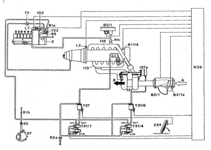
Functional diagram of the diesel injection system
1 - injection pump; 2 - Centrifugal regulator; 60 - EGR valve; 61a - Jet; 61b - Jet 0.5; 61s - Jet 0.7; 62 - Filter; 62a - Filter; 65 - Vacuum distributor; 67 - Vacuum pump; 72 - Vacuum valve; 103 - Aneroid compensator (ALDA); 110 - Exhaust manifold; 137 - Turbocharger; 137a - Vacuum boost pressure control actuator; 138 - Inlet pipeline; 224 - Accelerator pedal; В2/1 - Air flow sensor; B2 / 1a - Air temperature sensor in the intake manifold; В5/1 - Pressure sensor; B11 / 4 - Coolant temperature sensor; L3 - Sensor for the speed of rotation of the flywheel ring gear; L7 - Fuel line; N39 - Processor unit EDS; Y22 - Electromagnetic actuator of the electronic idle control system (ELR); Y27 - EGR switching valve; Y31/1 - EGR vacuum sensor; Y31 / 4 - Vacuum sensor of the boost pressure control system; Y31 / 6 - Shut-off valve of the boost pressure control system
Designations:
- A - intake air
- B - Exhaust gases
- a - the ventilation duct leading to the cabin
- c - Other vacuum consumers
Pneumatic connections on sensors
| VAC | Vacuum from the vacuum pump |
| ATM | Ventilation duct leading to the cabin |
| OUT | From sensor Y31/1 to recirculation change-over valve Y27 |
| OUT | From sensor Y31/4 to the vacuum actuator of the distributor valve that controls the air pressure |
The engine is controlled by an electronic system similar to that of a gasoline engine. The system controls the operation of the engine by analyzing information from a large number of sensors.
Diagram of the laying of vacuum connections
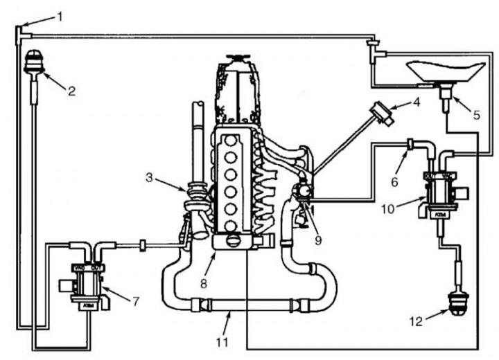
Diagram of laying vacuum lines (turbo diesel engine 3.0 l)
1 - To other vacuum consumers; 2 - Ventilation filter of the vacuum transducer for boost control / operation of the pressure control damper; 3 - Turbocharger; 4 - Pressure sensor; 5 - Control valve with a bore diameter of 8 mm; 6 - Connector; 7 - Vacuum transducer for boost control / pressure control damper operation; 8 - Vacuum pump; 9 - Exhaust gas recirculation valve (EGR); 10 - EGR valve vacuum transducer; 11 - Intercooler; 12 - EGR valve vacuum transducer vent filter
Diesel models do not have an accelerator cable. Instead, a pedal position sensor is installed on the pedal.
There is no fuel cut-off valve when the ignition is turned off. In order to turn off the engine when the ignition is turned off, the engine control unit sends a signal to the injection pump control unit, which, in turn, stops the fuel supply to the injectors.
The fuel system is designed to prevent «suction» air without fuel in the tank. The control unit constantly checks the fuel level in the tank, processing information from the fuel reserve sensor located in the tank. When the fuel supply drops to a certain level, the control unit lights up a warning lamp on the dashboard, after which it forcibly causes fuel skips, thereby limiting the maximum speed. This continues until the level of fuel in the tank exceeds the allowable mark.
Information about the position of the crankshaft and the speed of rotation of the engine enters the control unit from the crankshaft position sensor (CKP). The inductive sensor head is located opposite the flywheel and constantly scans special marks (36 pieces), applied to its surface. When the mark passes by the sensor head, it sends a pulse to the control unit. The marks are evenly applied to the surface of the flywheel, but one mark is missing. It should be located 90°before the TDC of the first cylinder. When the flywheel passes this point, the sensor does not send a pulse to the control unit. The unit recognizes this pause and accurately determines the TDC moment. The duration of this pause is used to determine the engine speed.
Information about the amount and temperature of the air entering the engine comes from the absolute pressure sensor in the intake manifold (MAP) and air temperature sensors. The absolute pressure sensor is connected to the pipeline by a vacuum hose and measures the pressure in it. Two air temperature sensors are installed. One is installed before the turbocharger and the other after the intercooler. Temperature and air pressure are used to calculate the exact amount of fuel that needs to be dropped to the injectors.
The traditional coolant temperature sensor has been replaced with a head temperature sensor. It measures the temperature of the head and sends the received information to the control unit. Analyzing this information, the control unit corrects the composition and injection timing of the fuel mixture, and also controls the cold engine warm-up system.
The brake light switch and brake pedal sensor inform the control unit of the current brake pedal position. When receiving signals from these sensors, the control system immediately switches the engine to idle until it receives a signal from the accelerator pedal position sensor.
The accelerator cable is missing. Instead, an accelerator pedal position sensor is installed. The sensor constantly informs the control unit about the position of the pedal, which, in turn, accurately calculates the injection parameters. The idle speed is also controlled by the control unit and cannot be adjusted manually. Analyzing information from various sensors, the control unit calculates the idle speed, correcting them depending on the load on the engine and its temperature.
The fuel injection system is a direct injection system. In the bottoms of the pistons there are vortex chambers that provide swirling of the fuel entering the combustion chambers. Injectors open in two stages to optimize fuel combustion (for this, there are two springs inside each nozzle). When the injector is opened, a small amount of fuel is drawn onto the internal components of the injector, lubricating them, and returns to the fuel tank.
The heating of a cold engine is controlled by the engine control unit. When the engine is cold, the injection timing is shifted by the control unit. The engine control unit, in turn, controls the operation of the glow plugs. Glow plugs are installed in each cylinder and are switched on before starting the engine, work while cranking the engine with a starter and for some time after starting the engine. Spark plugs make it much easier to start a cold engine. After switching on the ignition, the corresponding control lamp lights up on the dashboard (talk to Vehicle equipment, arrangement of instruments and controls Chapters Manual), signaling the inclusion of glow plugs. As soon as the lamp goes out, you can start the engine. If the ambient temperature is very low, the spark plugs continue to work for some time after the engine is started. This ensures stable operation of the engine and the reduction of harmful impurities in the exhaust gases.
Due to the good cold start performance of a direct injection engine, preheating is only required at temperatures below -10°C.
Fuel passes through the fuel filter. The filter separates the fuel from water and contaminants. Therefore, it is important to remove water from the fuel and replace the filter element in a timely manner.
The fuel system of diesel engines is very reliable. When using clean fuel and performing regular maintenance, it should function properly until the end of the vehicle's life. After very long mileage, the internal components of the injectors may wear out and need to be repaired. Since the pump - nozzles are of a complex design, repairs are recommended to be carried out in a specialized workshop.