
Swirl chamber injection system
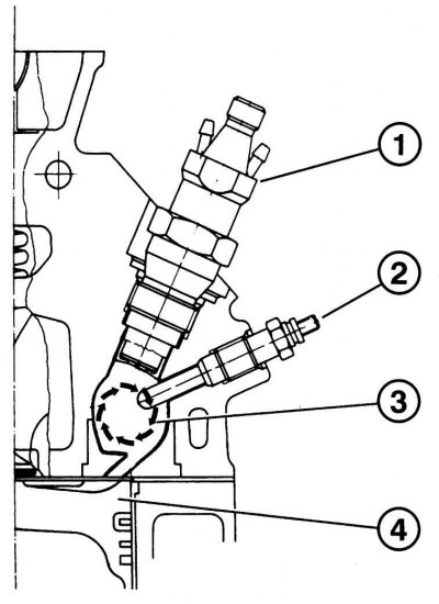
Pic. 4.60. Section of the cylinder head with swirl chamber: 1 - nozzle; 2 - glow plug; 3 - vortex chamber with an inlet channel; 4 - cylinder
For diesel engines with a vortex system (pic. 4.60) the combustion chamber is divided. The vortex chamber is connected to the over-piston space, and when the piston approaches the top point, a vortex flow is created in it, which effectively mixes the fuel with air. The mixture, ignited, passes into the main combustion chamber. Swirl chamber engines have proven themselves, especially at high speeds (more than 5000 min-1).
Prechamber injection system (antechamber)
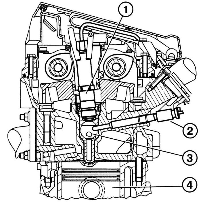
Pic. 4.61. Section of the cylinder head with prechamber: 1 - nozzle; 2 - glow plug; 3 – prechamber with inlet channel; 4-cylinder
With prechamber system (pic. 4.61), which is used on Mercedes diesel engines, the working chambers are divided, like the vortex system. The prechamber is located on top of the cylinder head. Ignition of the fuel in the combustion chamber occurs through thin nozzles coming from the prechamber.
Direct injection
With direct injection, fuel is injected into the combustion chamber and burns instantly.
This system is highly economical, but it has its drawbacks: a high level of engine noise, especially during start-up and a sharp increase in speed.
Common rail system
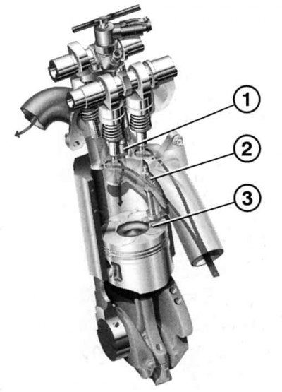
Pic. 4.62. Direct injection in the Common Rail system: 1 - nozzle; 2 – an inlet branch pipe; 3 - piston with a special groove
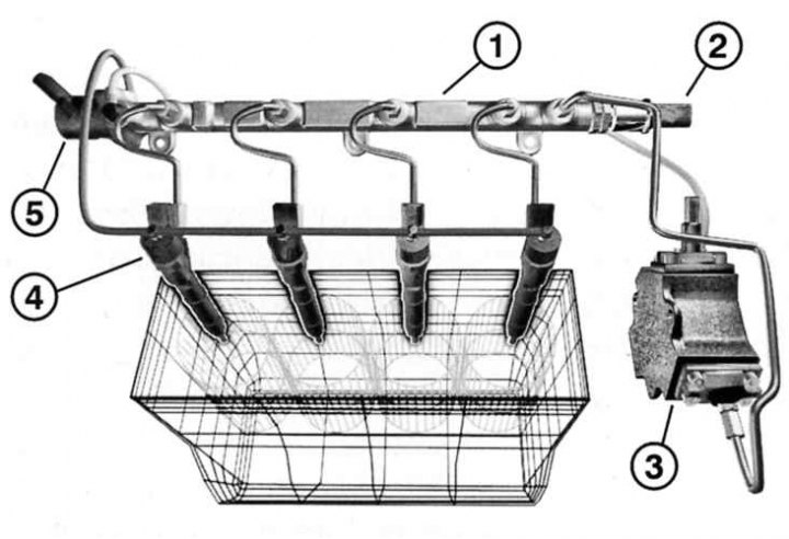
Pic. 4.63. Common rail system diagram: 1 - common fuel rail; 2 – pressure sensor; 3 - pump; 4 - nozzle; 5 - pressure control valve
common rail system (pic. 4.62, 4.63, 4.68) not only provides efficiency and minimal emission of environmentally harmful gases, but also surpasses modern diesel engines with prechamber injection in terms of comfort and engine noise level. Therefore, CDI diesel engines have taken a major place in the development of Mercedes-Benz engine building.
«Common Rail» means «General highway». If in systems with direct injection, fuel under pressure was supplied to each nozzle separately, then in the Common Rail system, the fuel, regardless of the injection sequence, is in a common fuel rail, the so-called accumulator.
Electronic control regulates the injection pressure depending on the engine speed and load. Sensors that receive data on the operating mode of the camshaft and crankshaft issue commands for optimal injection according to the operating mode of the engine. Moreover, the fuel supply and injection are independent of each other.
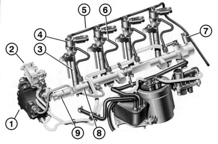
Pic. 4.64. The main elements of the Common Rail system: 1 - high pressure pump; 2 - pressure pump; 3 - nozzle; 4 - magnetic valve of the dosing system; 5 - return fuel line; 6 - high pressure pipeline; 7 - fuel pressure sensor; 8 – pressure accumulator; 9 - fuel pressure control valve
A feature of this development is a special drive (battery) 8 (pic. 4.64), which always maintains a pressure of up to 1350 bar. This is necessary so that the line that connects the pump to the injectors always has fuel at the right pressure, ready for injection.
The line connects to the injectors. Each injector has a magnetic valve that regulates the pressure and amount of fuel supply. The microcomputer controls the operation of the valve based on the operating mode and engine load. This system significantly increased the efficiency of the engine and contributed to a significant reduction in the emission of harmful gases into the atmosphere.
High pressure fuel pumps (injection pump)
High pressure fuel pumps are used to supply diesel fuel to injectors under high pressure (about 120 bar). 4- and 5-cylinder engines are equipped with a distribution injection pump. The 6-cylinder engine has an in-line injection pump. All injection pumps are located on the left side of the engine and are driven by a chain from the crankshaft. In this case, the frequency of rotation of the high-pressure fuel pump shaft is half the frequency of rotation of the crankshaft. High pressure fuel pumps are electronically controlled.
Injection pump of distribution type
The E 220 D and E 290 TD engines are equipped with a distributor-type injection pump (pic. 4.64, 4.65). The high pressure fuel pump has a built-in fuel priming pump and a temperature sensor, which gives a signal to stop the fuel supply. Solenoid valves are located outside, one for stopping the engine, the second for supplying fuel. The high-pressure fuel pump supplies fuel through thin channels to the corresponding cylinder.
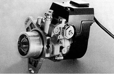
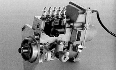
Pic. 4.65. Distribution injection pump for E 220D and E 290 TD models
The pump shaft is connected to the head channel, and the discharge pistons are separated from each other by fuel pressure (about 8 bar), until the lugs on the cam are exerting force on the bearing ends. During the rotation of the shaft, the discharge channel closes and the high pressure channel opens.
The distribution pump head contains 4 (or 5 for a 5-cylinder engine) injection channels and, accordingly, 4 (5) high pressure channels. As soon as the cams on the cam are aligned with the bearing lugs, the pistons begin to compress the fuel, the pressure rises, and when it reaches about 120 bar, injection occurs.
The amount of injected fuel is determined by the stroke length of the injection piston, which is controlled by the axial movement of the bearing lugs. The axial setting of the distributor pump shaft is controlled by two solenoid valves and a fuel quantity regulator return spring.
The fuel injection advance angle is controlled by the position of the cam in relation to the distribution pump head. By turning the washer against the direction of rotation, an earlier injection time is set, respectively in the direction of rotation - later. The rotation of the cam around the axis of the shaft is carried out with the help of an adjusting valve and a return spring. When set to position «early» the control valve will open, the pressure will increase and the control piston will move to the left. When the valve closes, the pressure decreases, and the piston moves to the right under the action of the spring.
Inline injection pumps
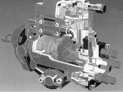
Pic. 4.66. Distribution injection pump installed on E 220 D and E 290 TD models, in section
On E 300 D models, an in-line injection pump is installed (pic. 4.66) with electronic control - ERE (Elektronisch geregeltes Reien-Einspritzsystem). In-line injection pumps have a separate pump section for each cylinder, which delivers fuel to the appropriate injector through a high-pressure steel pipeline. The main components of the ERE system are the in-line injection pump and the electronic control unit for the injection system.
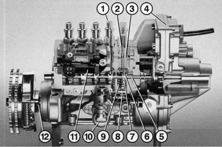
Pic. 4.68. Inline injection pump (ERE) in section: 1 - receiving part for connecting the high-pressure pipeline with the nozzle; 2 - discharge valve; 3 - plunger; 4 - mechanism for adjusting the number of revolutions (ERE); 5 - control rail; 6 - plunger installation lever; 7 - connector; 8 - roller pusher; 9 - plunger spring; 10 - fuel pump; 11 – electrohydraulic regulator; 12 - cam shaft
At the bottom of the pump is a camshaft 12 (pic. 4.68). With the help of its cams, the pump sections are actuated according to the injection sequence. The main parts of the pump section are: discharge valve 2, cylinder and plunger 3, rotary plunger sleeve and spring 9.
When the plunger is in the down position, the cavity above it is filled with fuel through the inlet. The cam of the pump shaft moves the pusher up, the plunger spring is compressed, the plunger closes the inlet, the pressure increases.
When the pressure reaches 120 bar, the nozzle needle rises and fuel enters the prechamber. Injection continues until the plunger opens the fuel control outlet. At this moment, the pressure above the plunger drops sharply, the discharge valve closes, having previously passed a small amount of fuel back into the cylinder. The pressure in the fuel pipe and injector drops sharply. The nozzle closes.
The plunger has a helical ground channel on the side surface, and depending on the position of the plunger, the fuel supply adjustment outlet remains closed for some time. The path that the plunger travels when the outlet is closed is called the injection stroke. The longer the injection stroke, the more fuel is injected into the engine cylinder.
The swivel bushings of the plungers of all pumping sections are connected via a short lever to the control rail. When assembling the pump, the swivel sleeves are installed in such a way that all pump sections deliver the same amount of fuel.
The fuel control rail is an important part of the injection pump, with the help of which the injected fuel is metered into each cylinder. The control rack is connected to the accelerator pedal via an electronically controlled speed controller (ERE).
Pic. 4.67. ERE in-line injection pump installed on the E 300D model
Speed controller
The electronic speed controller is located on the back of the fuel pump and controls the rack. The regulator is controlled by a rectangular pulse voltage with a frequency of about 190 Hz. Depending on the mode, the force of the actuating magnet changes, and, overcoming the force of the spring, it advances the rail in the direction «Start» or, respectively, «Volllast» (full load). The travel length of the rack is 19.5 mm.
Reduced engine noise
In the previously used injection pumps with direct injection at high pressure (up to 145 bar), the noise of the engine was much higher than that of the prechamber models. The Common Rail system before the main portion of fuel injects a small, so-called pilot dose of fuel, which provides «heating» combustion chambers. Thanks to this, optimal conditions are created for the ignition of the main fuel, it ignites much faster, since the pressure and temperature rise smoothly, and not abruptly. This affects not only the reduction of noise, but also the reduction of toxicity of exhaust gases.
Based on this, Mercedes-Benz specialists have taken additional measures to reduce the engine noise level. These include a special sound-absorbing casing (damper) cylinder heads and intake manifold, crankcase reinforcement and camshaft cover.