
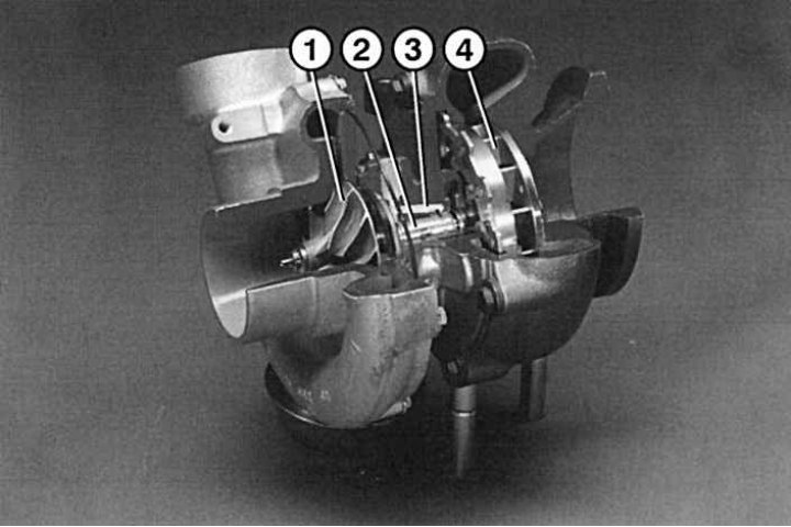
Pic. 4.75. Turbocharger in section (290TD): 1 - turbine; 2 - shaft; 3 - oil channel; 4 - compressor
The turbocharger housing is divided into two compartments: turbine 1 (pic. 4.75) and compressor 4. Each has an impeller. They sit rigidly on the same shaft 2. The turbine is driven by the flow of exhaust gases, the compressor pumps air through the pressure control valve body into the cylinders.
Charge air pressure regulator
Both turbine impellers can reach very high speeds, over 100,000 min-1. In this case, the charge air pressure can rise above 2 bar. Since this pressure is excessive, an air pressure regulator is installed on the compressor, which performs the function of reducing pressure.
When the turbine speed reaches about 50,000 min-1 and a small pressure is created, the regulator works in such a way that the pressure is kept constant even at low speeds, which helps to avoid «failures» with a sharp increase in speed.
If the pressure on the regulator at high loads rises above the set (0.9 bar), the membrane opens. In this case, only a small part of the exhaust gases will work for the turbine, and the rest will go into the muffler.
To maintain the required air pressure when driving at any altitude (in the mountains) sensor built into the control unit «raise». When driving in rarefied air, the sensor sends a signal to increase the pressure of the compressor and thereby maintains the normal mixing of air with fuel.
VTG turbocharger
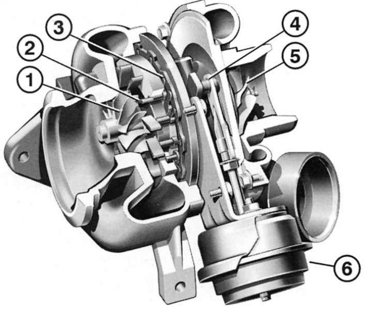
Pic. 4.76. Sectional view of VTG turbocharger: 1 - turbine impeller; 2 - exposed guide vanes; 3 - setting wheel blades; 4 – thrust with an adjusting lever; 5 - compressor impeller; 6 - vacuum chamber
4-cylinder common rail engines are equipped with so-called VTG turbochargers with variable turbine geometry (pic. 4.76).
In the VTG compressor, the air flow cross-section changes depending on the engine operating mode, due to which the optimum pressure is pumped. The optimum pressure is achieved by the control unit, depending on the installation characteristics of the turbine guide vanes inside the compressor.
At low engine speeds, the blades are covered, reducing the cross section of the air flow, and the pressure rises; At high speeds, the cross section increases and the pressure drops.
This achieves a number of advantages:
- 1. Changing the setting of the guide vanes allows you to optimally use the energy of the exhaust gases and achieve high efficiency due to the large selection of control characteristics.
- 2. Increasing the charge air pressure at low speeds. The turbocharger runs faster, thereby eliminating «failures» when going from low to high speeds.
- 3. Increasing torque due to better filling of the cylinders.
- 4. Reducing smoke at full load due to the presence of a reserve of forced air.
- 5. Improved discharge pressure dynamics.
- 6. Rejection of the charge air pressure control valve (waste gate).
- 7. Increased power due to increased discharge pressure at low speeds, hence optimal discharge control.
1. If the turbocharger is not working, this may be due to a quick shutdown of a hot engine immediately after a long drive at maximum speed. In this mode, coking of the compressor can occur: the shaft bearings, especially on the side of the exhaust gas turbine, overheat greatly, oil burns out in them, and they can boil. If this happens frequently, the bearings will fail and need to be replaced. Therefore, never immediately after a long movement at maximum loads, do not turn off the engine, let it idle for some more time.
2. Never run the engine without an air filter, small solid particles can damage the compressor (turbine rotation speed around the perimeter - up to 500 m/s). Before changing the compressor, it is necessary to check the operation of the following components (according to the cause of the malfunction): ignition, power supply system, compression, air filter and tightness of the connections of the air injection system and the exhaust system.
Charge air cooler
An air cooling radiator located between the turbocharger and the pressure control valve housing is connected to the engine cooling circuit. If the air in the compressor reaches a temperature of +110°C, then, passing through the radiator, it is cooled to +70°C.
In the mixing chamber behind the radiator, clean air is mixed with the exhaust gases in a computer-calculated ratio to optimize engine performance. To do this, the mixing chamber is equipped with a special exhaust gas valve and a throttle valve, which is controlled by an electro-pneumatic converter. Throttling the air increases the pressure difference between the intake air and the exhaust gases and thus affects the performance of the exhaust gas system.
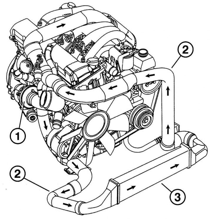
Pic. 4.77. Air flow direction (shown by arrows): 1 - turbocharger; 2 - branch pipes; 3 - radiator
Cleaning the charge air cooler
"30,000 km"
Clean the charge air cooling radiator during the summer period of vehicle operation. This operation is performed in the same way as with the radiator of the cooling system.