
Pneumatic Idle Speed Boost System
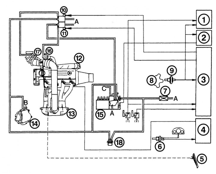
Pic. 4.73. Diagram of vacuum lines and valves: 1 - control module for the operation of the air conditioner compressor; 2 - switching smoothness control module (ARA); 3 - exhaust gas control module (ARF); 4 – heating system control module; 5 - gas pedal; 6 - coolant temperature sensor; 7 - choke with filter; 8 - flywheel; 9 - speed sensor of the starter gear; 10 - bypass pressure control valve; 11 - bypass valve for exhaust gases; 12 - exhaust manifold; 13 - suction pipeline; 14 - vacuum pump; 15 - injection pump; 16 - exhaust gas valve; 17 - pressure control valve body; 18 - thermal valve; A - blowing; B - side consumers; C - stop the engine
The system acts through a vacuum chamber on the idle speed controller in the injection pump. When the coolant temperature is less than +30°C, the idle speed is increased by approximately 100 min-1. The scheme in fig. 4.73 shows the operation of the thermal valve. When the valve is open, a vacuum acts on the diaphragm. The idle speed remains constant. When the valve is closed, the vacuum chamber communicates with the atmosphere through a vented tube, and the speed increases.
Checking the pneumatic system of the idle speed
The check consists in checking the tightness of individual pipelines by purging. If the vacuum chamber is damaged, it must be replaced.
1. Disconnect the pipeline from the vacuum chamber. With a good diaphragm, blowing and suction are not possible.
2. When the coolant temperature is below 30°C, the valve should be ajar, at a higher temperature it should be closed. The valve is located on the left side of the cylinder head.
3. When a pressure of 0.5 bar is applied to the pipeline to the vacuum chamber, the idle speed must increase by 100 min-1.
Electronic idle speed control
To adjust the idle speed, the sensor on the starter gear measures the exact number of revolutions of the crankshaft and sends a signal to the control unit. The control unit monitors the difference between the required and current values and regulates the number of revolutions depending on the engine load. When the coolant temperature is below +60°C, the idle speed increases according to the specified parameters. For this, a pulsed voltage-controlled electromaterial is used, which acts on the high-pressure fuel pump regulator. To protect against power surges, a 10-amp fuse is installed in the control unit.
Checking the electronic idle speed control
If the idle speed is not working properly or if it stops after starting the engine, check the electronic control system
1. Make sure that the accelerator drive is installed correctly - when the pedal is released, the drive (cable) swing arm must be free.
2. Let the warm engine idle and disconnect the solenoid plug for about 3 seconds. When disconnecting the plug, the speed should increase briefly.
3. If the speed has not changed, briefly connect a voltage of 12 V to the electromagnet (for a maximum of 3 s to avoid coil burnout). If the RPM does not increase, replace the solenoid.