
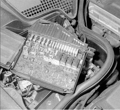
Pic. 4.69. Control block
Control block (pic. 4.69) mounted on the right side of the unit. It performs the following functions: providing the required amount of fuel, maintaining the speed, controlling the tempomat, diagnostics, monitoring the function «inlet-outlet» and determining the degree of system malfunction.
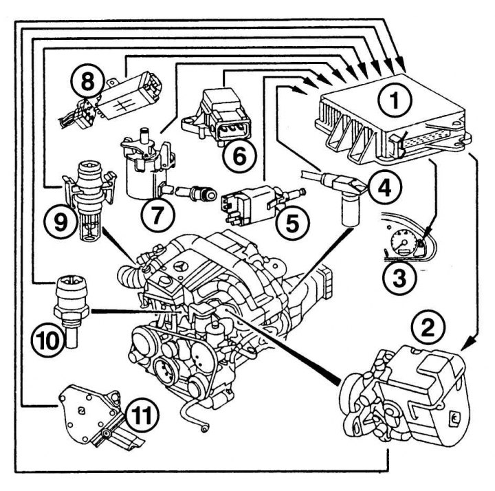
Pic. 4.70. Elements of the electronic control system: 1 - control unit; 2 - injection pump; 3 - control lamp of the operating mode; 4 - sensor indicating the location of the crankshaft; 5 - stop signal; 6 - intake air temperature sensor; 7 - fuel supply sensor; 8 - safety relay; 9 - exhaust gas valve; 10 - coolant temperature sensor; 11 - switch signal lock and reverse
Input signals come from the following sensors (pic. 4.70): crankshaft position indicator (at the starter), positions of the starter working gear (below the gearbox housing), position sensor and accelerator pedal position sensor, suction pressure sensor, intake air temperature sensor, coolant temperature sensor, charge fuel temperature sensor (in the pump), brake light, ABS signal activation sensor, starter operation status sensor in running engine mode (for automatic transmissions).
The output signals of these sensors control: stop, speed control, ARF valve shift, discharge valve position, shift valve in automatic transmission, EDC diesel mode status (instrument panel lamp), air conditioning control and fault characteristics when connecting the diagnostic tool.
All problems in the system are noted self-diagnosis system in computer memory. If the problem continues for a long time, then the warning lamps on the instrument panel come on. Separate «mistakes» the control system can fix it, but it will remain in the computer's memory. The control unit in a critical situation will drown it out or set the optimal speed to continue driving. If the lamp lights up «EDS», it is necessary to go to a car repair shop, since only there they carry out high-quality diagnostics and repairs.
All models are equipped with new systems that are controlled by a microcomputer in cooperation with the so-called CAN bus (Controller Area Network), which plays the role «counting and distributing apparatus» and sends signals to the computer. Electronic control is the main element in the Common Rail system, which will work without interruption with regular maintenance.
coolant temperature sensor screwed into the front of the cylinder head and indicates the coolant temperature. Resistance at +80°C is 300 Ohm, at +20°C - 2.5 kOhm.
Fuel temperature sensor in model 220-D it is located on the injection pump and mounted in the split shaft position sensor section. For a 5-cylinder diesel, it is located on the stop mechanism. This sensor determines the temperature of the fuel for the subsequent calculation of its density. It also generates a signal when the coolant temperature sensor fails.
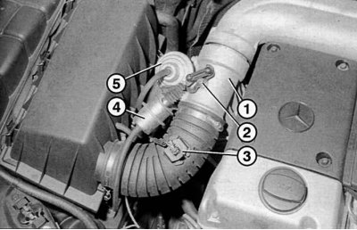
Pic. 4.71. Control units of the air intake system: 1 - pressure valve body; 2 - valve shaft with a lever; 3 - intake air temperature sensor; 4 - vacuum chamber of the control valve; 5 - vacuum chamber for exhaust gases (ARF)
Signal from intake air temperature sensor (pic. 4.71) serves to calculate the mass of air when adjusting the amount of injected fuel, correcting smoke, removing exhaust gases and adjusting the charge air pressure. Resistance at +20°C - about 6 kOhm, at +40°C - about 2.6 kOhm.
Mass air flow meter (CDI). Information about the mass of intake air is needed to calculate the fuel injection mixture. Regardless of the air temperature, the measurement is made as follows. A suction element is integrated into the suction system (heated plate), which is cooled by the intake air stream. Depending on the strength of the flow, it changes its temperature and resistance. The electrical value of the change in resistance is output to the control unit.
crankshaft position sensor serves to determine the number of revolutions and position of the crankshaft. Located on the gearbox housing above the starter.
Four (five for 5-cylinder engines) segments on the flywheel when the engine is running, an alternating voltage is given to the sensor. The higher the RPM, the higher the voltage. If the segment passes the sensor with the front edge, there is a positive voltage jump, if with the back edge - negative.
Starter gear position sensor installed only on 5-cylinder models and indicates the number of revolutions. Located on the bottom of the gearbox housing.
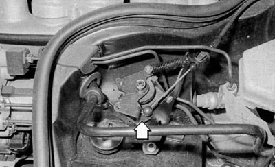
Pic. 4.72. Fuel supply sensor
Fuel supply sensor (pic. 4.72). The injection pump is not directly connected to the accelerator pedal. The fuel supply sensor is installed in a protective housing and connected to the pedal by a flexible drive. Mounted in the sensor: speed potentiometer, idle contact and return spring. On automatic transmission models, a modulated shift pressure valve is also installed.
Brake light switch. When braking, the control unit receives a signal, turns off the cruise control and gives a command to stop the maximum fuel supply. This avoids «run» vehicle even if the accelerator pedal is pressed by mistake. The same thing happens when you press the clutch pedal.
Clutch pedal switch. On 5-cylinder diesel engines, when the clutch pedal is pressed, the control unit signals the progress of the gear change and the activation of the vibration damper.
Suction pipe pressure sensor is located on the left side of the engine compartment and is connected to the suction pipe through a hose. The pressure in the suction line is required for the following functions: Limitation of maximum loads, exhaust gas evacuation (ARF) and regulation of intake air pressure. In addition, on the E 290 TD it displays information for adjusting the charge air of the turbocharger.
Charge air regulator (290 TD) operates with an electro-pneumatic valve. How it works: The charge air limiting solenoid valve is controlled by the flow of compressed air through the valve on the compressor - when the valve is opened, the pressure drops.
Injection pump camshaft position sensor (4 cylinder diesel engine) responds to the longitudinal displacement of the camshaft relative to the drive shaft and consists of a coil with a core.
The core is screwed into a hollow camshaft. When the shaft shifts, the core changes the inductance of the coil. This is an important characteristic for adjusting the amount of fuel supply.
Cam Position Sensor (4 cylinder diesel engine) also consists of a coil with a core. The core is inserted into the piston. The coil is mounted in the housing of the distribution injection pump. The cam, rotating, makes translational movements back and forth, as a result of which the inductance of the coil changes and a signal is given that controls the adjustment of the injection of fuel.
Rack travel sensor (5 cylinder diesel engine) transmits data on the position of the fuel control rail to the control unit. The sensor is mounted in the speed controller of the in-line injection pump. When the ignition is switched on, the rack occupies «starting» position (maximum rail stroke length - 19.5 mm). When the position of the rail changes, the distance between the coil and the short-circuited washer changes, as a result of which the inductance changes.