
The location of the components of the electronic engine management system (IFI)
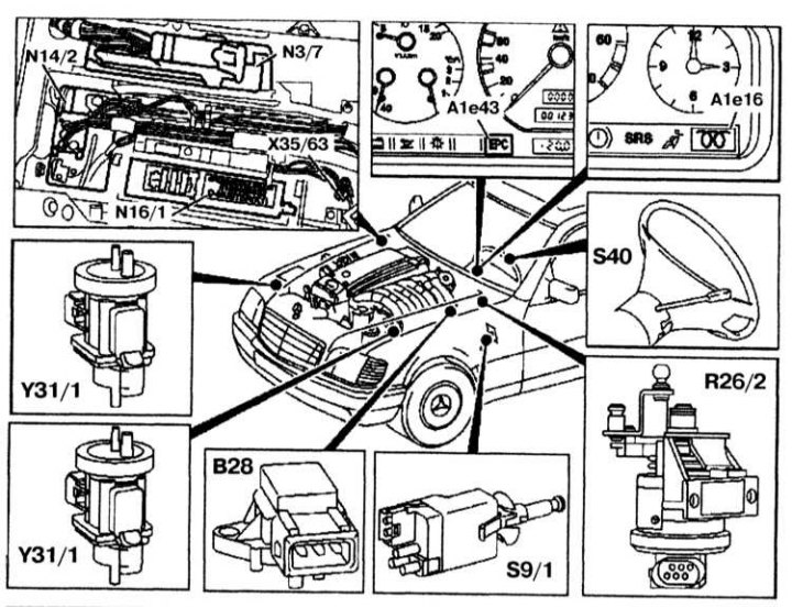
The layout of the components of the electronic engine control system (IFI)
A1e16 - Pre-glow signal lamp; A1e43 - Signal lamp EPC; B28 - Pressure sensor; N3/7 - IFI control unit; N16/1 - Main unit; N14 / 2 - Output pre-heating unit; Х35/63 - Control unit box; R25 / 2 - Accelerator pedal position sensor; S40 - Tempostat; Y31/1 - EGR system converter; Y31 / 5 - Boost pressure control unit / control converter damper; 29/1 - Stoplight switch
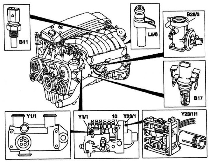
IFI component layout
B11 - Coolant temperature sensor; B17 - Inlet air temperature sensor; B28 / 3 - EGR system lift sensor; L5 / 6 - Crankshaft position sensor; Y1/1 - Electro-hydraulic shut-off valve IFI; Y23 / 1 - Actuator for controlling the amount of injected fuel; Y23/1/1 - Rail position sensor; 10 - Inline injection pump
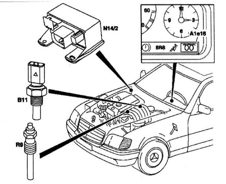
Location of IFI components
A1e16 - Signal lamp pre-glow; 811 - Coolant temperature sensor; N14 / 2 - Output block of the pre-heating system; R9 - Glow plugs