
General information
Turbocharger design (on the example of engine 603.971)
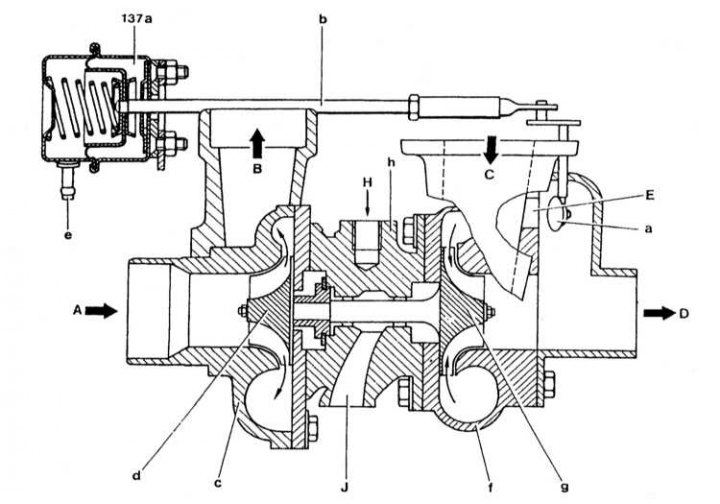
137a - Pneumatic actuator of the valve that controls the boost pressure; A - Intake air; B - Compressed air; C - Exhaust gases rotating the turbine wheel; D - Exhaust gas output; E - Turbocharger bypass valve; H - Pressure oil pipeline; J - Oil return line; a - Turbocharger bypass valve; b - stem; c - Compressor housing; d - Compressor impeller; e - Connection to the control line; a - Turbine housing; g - Turbine impeller; h - Turbocharger housing
The turbocharger is designed to increase engine power by increasing the air pressure in the intake manifold. Air does not just enter the cylinders, but is supplied to them under pressure. In accordance with the increase in air supply, the injection pump increases the fuel supply.
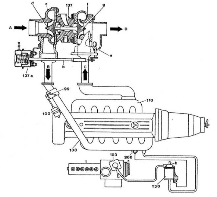
Functional diagram of boost control (engine 603.971)
В5/1 - Pressure sensor; 1 - injection pump; 103 - Aneroid compensator (ALDA); 110 - Exhaust manifold; 137 - Turbocharger; 137a - Pneumatic actuator of the boost pressure control valve; 138 - Inlet pipeline; A - Intake air; B - Compressed air; C - Exhaust gases rotating the turbine wheel; D - Exhaust outlet
The compressor turbine is driven by the exhaust gases. Gases passing through a special casing (compressor casing), are fed to the compressor turbine. The turbine rotates on a shaft, at the other end of which there is a compressor wheel in a separate casing. It is he who supplies air under pressure to the pipeline.
An intercooler of compressed air is installed between the compressor and the pipeline (intercooler). In the intercooler, the air is cooled, compressing at the same time. The partial pressure of oxygen increases, resulting in an increase in engine power.
The air pressure in the pipeline is limited by a special sensor. When the pressure limit is reached, the sensor opens the damper, thereby limiting the flow of exhaust gases to the turbine.
The compressor shaft is lubricated with engine oil, which is supplied through a specially designed hose. Shaft constantly «floats» In oil. Oil is drained from the compressor to the sump through the return hose.
The turbocharger is an integral part of the exhaust manifold and cannot be separated from it.
Precautionary measures
The rotation speed of the compressor turbines is huge, and the operating temperature is very high. To avoid personal injury and damage to the turbocharger, observe the following precautions:
- Do not start the engine after removing any component of the turbocharger. The ingress of foreign objects on the turbine blades can lead to the failure of the latter. You also risk injury from objects thrown from the turbine;
- After removing any turbocharger components or air intake hoses, cover it with a clean rag;
- Do not give gas immediately after starting the engine, especially if it is not warmed up. Oil cannot instantly lubricate the turbine shaft;
- Never turn off the ignition immediately after stopping the vehicle. Do not press the accelerator pedal before stopping the engine. Immediately after the ignition is turned off, the oil stops supplying to the compressor shaft and for some time it will rotate without lubrication;
- Before turning off the engine, let it idle for several minutes, during which the turbine speed will decrease significantly;
- Change the oil, oil filter and air cleaner regularly. The use of old oil will lead to the formation of deposits on the compressor shaft and its failure. Thoroughly clean nearby surfaces before disconnecting oil supply and return hoses from the compressor. Store removed components in airtight containers.
For removal and installation, also refer to Sections Removal and installation of a turbocharger and Air blower - installation details.