
Petrol models
Left manifold
Models 463.249/250

Installation details of the left exhaust manifold on models 463.250 (M112)
1 - Left exhaust manifold; 2 - Fixing nuts; 3 - Bolts; 4 - Sealing gasket; 5 - Heat shield (upper section); 6 - Heat shield (bottom section); 7 - Ignition coils; 9 - Bolts of the bracket of the transverse section of the exhaust system; 10 - The lower section of the exhaust system; G3 / 3 - Left pre-catalytic lambda probe; G3/3x1 - Electrical wiring connector for the left pre-catalytic lambda probe
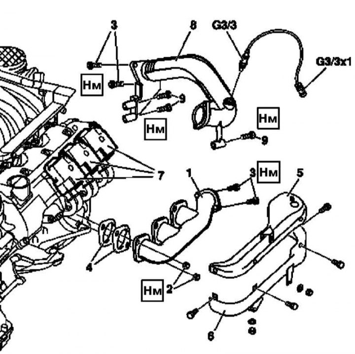
Installation details of the left exhaust manifold on models 463.249 (M113)
1 - Left exhaust manifold; 2 - Fixing nuts; 3 - Bolts; 4 - Sealing gaskets; 5 - Heat shield (upper section); 6 - Heat shield (lower section); 7 - Ignition coils; 8 - The lower section of the exhaust system; 9 - Bolts of the bracket of the transverse section of the exhaust system; G3 / 3 - Left pre-catalytic lambda probe; G3/3x1 - Electrical wiring connector for the left pre-catalytic lambda probe
1. Disconnect the negative cable from the battery.
2. Remove the cover of the power unit with built-in air cleaner (see Section Removal and installation of components of an inlet air path).
3. Remove left ignition coils (see chapter Engine Electrical Systems).
4. On models 463.250 (M112) in order to provide access to the bolts of the transverse section of the exhaust system, remove the left pre-catalytic lambda probe (G3/3) with electrical wiring connected to it (G3/3x1).
5. Remove the top section of the heat shield (5).
Note. The screen consists of two sections bolted to each other.
6. On models 463.249 (M113) Disconnect the throttle cable from the controller.
7. Release the flange connection of the fastening of the cross section of the exhaust system (10/8) to the left exhaust manifold (1).
8. Turn out bolts (9) fastening the lower section of the exhaust system to the transmission housing.
9. Remove the bottom section of the heat shield (6).
10. Give nuts (2) and remove the left exhaust manifold (1), - prepare replacement nuts (2), gaskets (4) and hairpins.
11. Installation is carried out in the reverse order.
12. In conclusion, clear the memory of the processor of the on-board self-diagnosis system (see chapter Engine Electrical Systems).
Models 463.246 (G55 AMG)
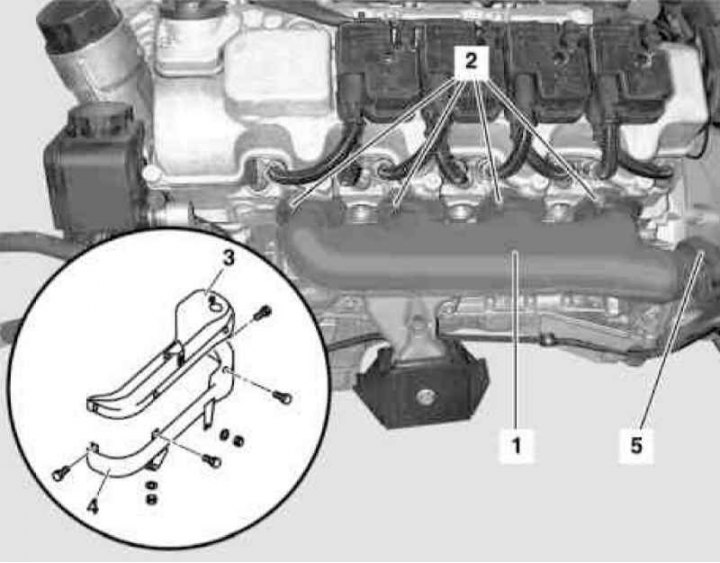
Installation details of the left exhaust manifold on models 463.246 (G55 AMG)
1 - Left exhaust manifold; 2 - Fixing nuts; 3 - Heat shield (upper section); 4 - Heat shield (bottom section); 5 - Flange connection of the lower section of the exhaust system
1. Disconnect the negative cable from the battery.
2. Remove the cover of the power unit with a built-in air cleaner (see Section Removal and installation of components of an inlet air path).
3. Remove the left dokatalitichesky lambda probe with the electroconducting connected to it.
4. Remove the top section of the heat shield (3).
5. Disconnect the throttle cable from the controller.
6. Loosen the flange connection (5) fastening the lower section of the exhaust system, - if necessary, replace the nuts.
7. Remove the bottom section of the heat shield (4).
8. Give eight fixing nuts (2) and remove the left exhaust manifold (1).
9. Installation is carried out in the reverse order.
10. In conclusion, clear the memory of the processor of the on-board self-diagnosis system (see chapter Engine Electrical Systems).
Right manifold
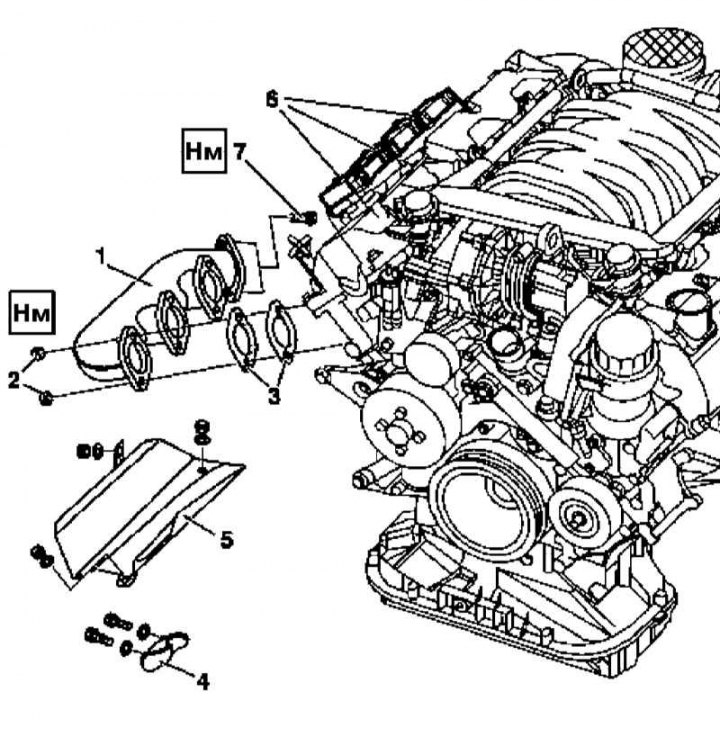
Installation details of the right exhaust manifold on petrol models (on the example of the M112 engine)
1 - Right exhaust manifold; 2 - Fixing nuts; 3 - Sealing gaskets; 4 - Heat shield of the generator; 5 - Thermal protection screen; 6 - Ignition coils; 7 - Bolts
1. Disconnect the negative cable from the battery.
2. Remove the air cleaner (see Section Removal and installation of components of an inlet air path).
3. Remove the right ignition coils (see chapter Engine Electrical Systems).
4. Remove the heat shield installed under the manifold (5).
5. Remove the generator heat shield (4).
6. On models 463.250 (M112) separate the front section of the exhaust system from the exhaust manifold, - if necessary, replace the bolt nuts (7).
7. On models 463.249/246 (M113) remove the flange connections on the left and right on the front section of the exhaust system.
8. Give fixing nuts (2) and, moving up, remove the right exhaust manifold (1).
9. Installation is carried out in the reverse order. Don't forget to replace the nuts (2), gaskets (3) and hairpins.
Diesel models
Models 463.323 (M612)
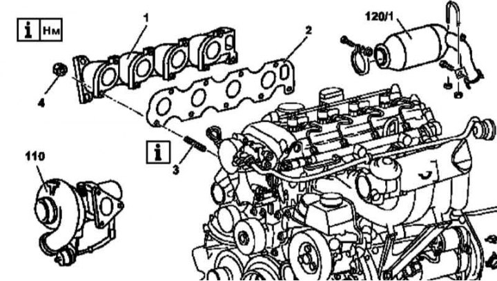
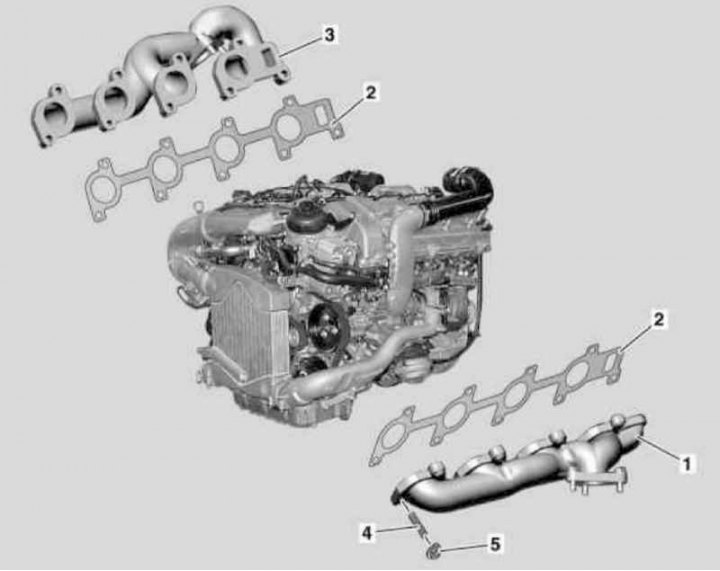
Details of installation of an exhaust manifold on diesel models 463.323 (M612)
1 - Exhaust manifold; 2 - Sealing gasket; 3 - Studs; 4 - Self-locking nuts; 110 - Turbocharger; 120/1 - Primary catalytic converter
1. Remove the catalytic converter (see Section Removal and installation of system of release of the fulfilled gases).
2. Remove the turbocharger (see Section Servicing Air Inlet Components).
3. Remove the ATF dipstick guide tube bracket (do not remove the dipstick).
4. Give self-locking nuts (4) and, moving aside the ATF dipstick guide tube, remove the exhaust manifold (1), - nuts must be replaced without fail.
5. Installation is carried out in the reverse order.
Models 463.333 (M628)
Installation details of exhaust manifolds on diesel models 463.333 (M628)
1 - Left exhaust manifold; 2 - Sealing gaskets; 3 - Right exhaust manifold; 4 - Studs; 5 - Self-locking nuts
1. Remove the turbocharger (see Section Servicing Air Inlet Components).
2. Give fixing nuts (5) and remove the exhaust manifolds (1 and 3) and their seals (2), - nuts must be replaced without fail.
3. Installation is carried out in the reverse order - check the condition of the mounting studs (4), replace damaged fasteners.