
Diesel models 463.333 (M628)
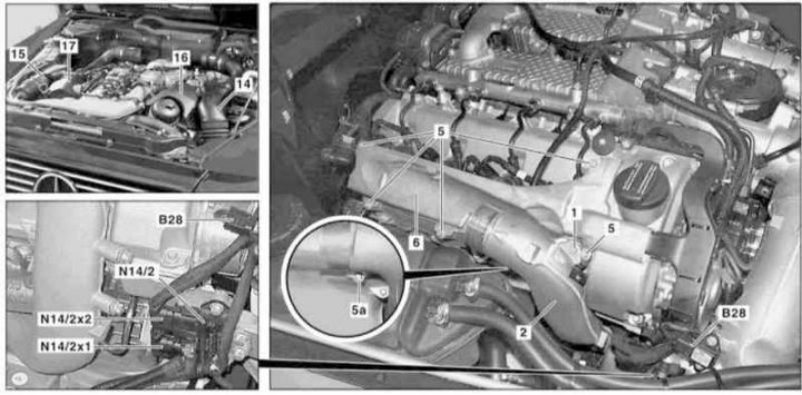
Installation details of the coolant temperature sensor of the CDI control system of the M628 engine (1 of 2)
1, 5, 5a - Bolts; 2 - Air duct; 6 - Cover; 14 - Left intake duct; 15 - Right intake duct; 16 - Finishing panel of the left cylinder head; 17 - Panel trim right cylinder head; B28 - Pressure sensor; N14 / 2 - Block output voltage of the preheating system; N14/2x1, N14/2x2 - Output voltage connectors
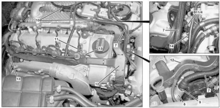
Installation details of the coolant temperature sensor of the CDI control system of the M628 engine (2 of 2)
7 - Vacuum line; 8 - Vacuum pump; 9 - Locking tabs; 10 - Clips; 11 - Bolt; 12 - Cable sleeve; 13 - Guide pins; 14 - Mounting clamp; B11 / 4 - Coolant temperature sensor
1. Remove the air cleaner (see Section Servicing Air Inlet Components).
2. Remove the right air intake with MAF sensor (B2/7) (see Section Servicing Air Inlet Components).
3. Release the duct (15) from clips in the wheel arch.
4. Remove the right cylinder head trim panel (17).
5. Remove the bolt (1) and move aside the air duct (2).
6. Remove the bolt (5a) and remove the cover (6).
7. Disconnect the electrical wiring from the pressure sensor (B28).
8. Disconnect connectors (N14/2x1 and N14/2x2) on the output voltage block of the preheating system (N14/2).
9. Squeezing the locking tabs (9), disconnect from the vacuum pump (8) line (7).
10. Release the latches (10) and slide the vacuum line (7) to the side.
11. Remove the bolt (11).
12. Remove from guide pins (13) cable sleeve (12) and open it to provide access to the coolant temperature sensor wiring connector (B11/4).
13. Squeezing the clamp with a screwdriver (14), remove the coolant temperature sensor (B11/4), - Prepare to collect spilled liquid.
14. Installation is carried out in the reverse order - do not forget to replace the sealing elements.
15. In conclusion, clear the memory of the processor of the on-board self-diagnosis system (see chapter Engine Electrical Systems).