
Petrol models
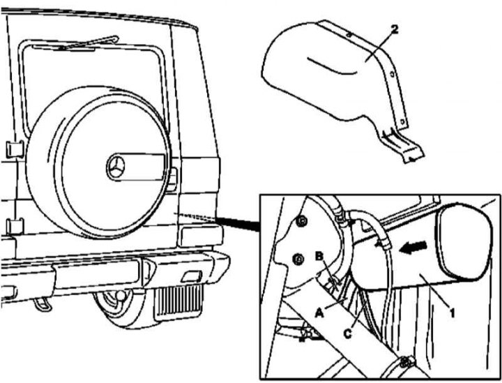
EVAP charcoal canister installation details (petrol models)
1 - Coal adsorber; 2 - Wheel arch protection locker; A - Compensation hole; B - Line to the compensation valve; C - Line to regeneration valve

Charcoal adsorber connection diagram
1 - Fuel distributor; 2 - Inlet pipeline; 3 - Fuel tank; 4 - Fuel filter; 5 - Coal adsorber; 6 - Compensation valve; 7 - Compensation line; 8 - Ventilation line; M16 / 6 - Throttle actuator actuator; M3 - Fuel pump; Y58/1 - Canister purge valve; A - Line: adsorber - purge valve; B - Line: purge valve —› inlet pipeline; C - Line: compensating valve -› adsorber; D - Line: fuel tank -› compensation valve; Е - Line: fuel filter —› tank degassing; F - Line: Fuel return line
1. Remove the locker (2) protection of the arch of the right rear wheel (see chapter Body).
2. Sliding in the direction indicated by the arrow in the illustration, remove the adsorber (1).
3. Disconnect from adsorber (1) lines (A, B and C).
4. Installation is carried out in the reverse order.