
Diesel models
Models 463.323 (M612)
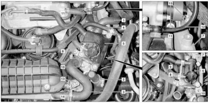
Installation details of the EGR cooler on models 463.323 (1 of 2)
1, 2, 3 - Hoses of the cooling path; 4 - Vacuum line; 5 - Cover; 6 - Fuel heating device; 7 - EGR cooler; 8, 10, 13, 15 - Bolts; 11 - Hollow bolt of the union connection; 12 - Fuel return line; 14 - Bracket
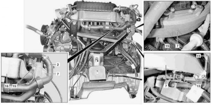
Installation details of the EGR cooler on models 463.323 (2 of 2)
16 — System of release of the fulfilled gases
1. Empty the cooling system (see chapter Ongoing care and maintenance).
2. Remove panels of finishing of a cover of a head of cylinders.
3. Disconnect the coolant hoses (1, 2 and 3).
4. Disconnect the vacuum line (4), move it together with the mounting clamp to the side and remove the cover (5).
5. Loosen the bolt (8) on bracket (9), remove the bolt (10) and disconnect from the cooler (7) fuel heating device (6).
6. Turn out a hollow bolt of union connection (11) fuel return line fittings (12) to the fuel line.
7. Turn out bolts (13) bracket mounting (14) and cooler (7). Remove bracket (14).
8. Unscrew from the cylinder head and exhaust system (16) and remove the cooler (7).
9. Installation is carried out in the reverse order - do not forget to replace the sealing elements.
10. In conclusion, check the components of the power supply and engine cooling systems for signs of leak development.
Models 463.333 (M628)
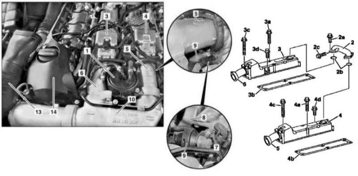
Installation details of the EGR cooler on models 463.333 (1 of 2)
1 - Fuel filter; 2 - Connecting pipe; 2a, 2c, 3a, 3c, 3d, 4a, 4c, 4d, 7 - Bolts; 2b, 3b, 4b - Gaskets; 3 - Right upper section of the air distributor; 4 - Left upper section of the air distributor; 5 - Left intermediate air duct; 6 - Right intermediate air duct; 8 - EGR cooler; 9 - Vacuum drive blocks for shutting off inlet ports; 10 - Throttle actuator actuator with upper air ducts; 13 - Right intake duct; 14 - Oil filler trim panel
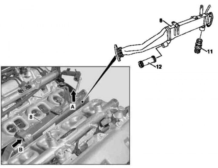
Installation details of the EGR cooler on models 463.333 (2 of 2)
11, 12 - Connecting pipes
And — the Direction of removal of a cooler
B - Cooler removal direction
1. Remove the crankcase protection.
2. Empty the cooling system (see chapter Ongoing care and maintenance).
3. Remove the air cleaner (see Section Servicing Air Inlet Components).
4. Remove the right intake duct (13) (see Section Servicing Air Inlet Components).
5. Remove the oil filler trim panel (14).
6. Remove fuel filter (1), - the filter must be replaced without fail.
7. Remove the left and right air intakes assembly with MAF sensors (see Section Servicing Air Inlet Components).
8. Remove the throttle actuator assembly with the upper air ducts (10) (see Section Servicing Air Inlet Components).
9. Remove the valve assembly (see Section Removal and installation of valve assembly).
10. Remove the EGR positioner (see Section Removal and installation of EGR positioners).
11. Turn out bolts (2a and 2c) and remove the right connecting pipe (2). Prepare replacement gaskets (2b).
12. Turn out bolts (3a, 3c and 3d) and remove the upper half of the right section of the air distributor (3). Prepare replacement gaskets (3b).
13. Turn out bolts (4a, 4c and 4d) and remove the upper half of the left section of the air distributor (4). Prepare replacement gaskets (4b).
14. Disconnect the vacuum hoses from the vacuum blocks (9) shutdown of the right and left inlet ports.
15. Remove the bolt (7) and screw off the assembly of the vacuum blocks (9) with a device for disconnecting the left inlet port from the air distributor.
16. First pull up the back side (A) EGR cooler (8), then push back the front side of it (IN) and remove the cooler (7) from connecting pipes (11 and 12). Prepare replacement O-rings if necessary.
17. Installation is carried out in the reverse order.