
Based on the information coming from the sensors of the system and the control algorithm stored in the memory, the unit generates control actions (in the form of impulses, constant voltages) and information messages (signals to the instrument cluster, to the diagnostic connector, etc.). These signals are sent to the actuators and to the elements of the information interface both through a simple electrical wiring and through a multiplex network (CAN-C).
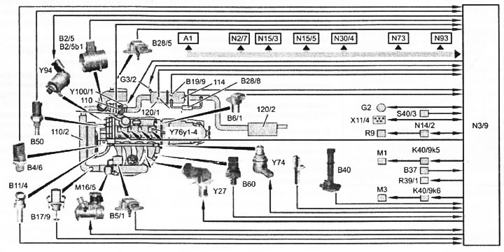
VN 9.008 A1. Instrument cluster; B2/5. Incoming air mass sensor; B2/5Y. Inlet air temperature sensor; B4/6. Pressure sensor in TKVD; 85/1. Boost pressure sensor; B6/1. Camshaft position sensor; B11 /4. coolant temperature sensor; B17/9. Charge air temperature sensor; B19/9. Exhaust gas temperature sensor; B28/5. Output pressure sensor in the air filter; B28/8. Exhaust gas differential pressure sensor on the particulate filter (DPF); B37. Accelerator pedal position sensor; B40. Combined oil condition sensor; 850. Fuel temperature sensor; 860. Back pressure sensor in the exhaust tract; G2. Generator; G3/2. Inlet oxygen sensor on the exhaust gas converter; K40/9kb. Starter relay; K40/9kb. Fuel pump relay; L5. crankshaft position sensor; M1. Starter; M3. Fuel pump; N2/7. The control unit of the passive security system; N3/9. CDI system control unit; N14/2. Glow plug output stage; N15/3. ETC system control unit (for automatic transmission); N15/5. Electronic gear selector control unit (for automatic transmission); N30/4. ESP system control unit; N73/ EIS control unit (EZS); R9. glow plugs; X11/4. External multiplex network connector; Y74. Pressure control valve in TKVD Y76/1-Y76/4. Fuel injectors 1-4 cylinders; Y83. Fuel cut-off valve; Y94. Fuel quantity control valve; CAN. Multiplex network (CAN-C)