
Operating principle of CAN·multiplex network
Previously used cable connection of individual electrical and electronic devices (standard cable connection) causes a direct connection of each control unit with all sensors and actuators from which this unit received measured values or which it controlled. Under certain circumstances, this can lead to excessive length or duplication of cable lines. Compared to standard cabling, the data bus offers the following advantages.
1. The wires from the sensors must only be routed to the nearest control unit, which converts the measured values into a data packet and transfers it to the CAN data bus.
In this case, some other control unit can control the servo mechanism, which receives the corresponding data packet via the CAN data bus and, based on it, calculates the value of the control action on the servo mechanism.
2. Signals from one sensor (e.g. from the coolant temperature sensor) can be used by different systems.
3. Improving diagnostic capabilities. Since signals from one sensor (e.g. speed signal) are used by different systems, then if a fault message is issued by all systems using this signal, the sensor or control unit that processes its signals is usually faulty. If a fault message is received from only one system, although this signal is also used by other systems, then the cause of the fault is most often contained in the processing control unit or actuator.
4. High data rate up to 1Mbps at max, line length 40m (currently not used on Mercedes Benz vehicles). The data transfer rate on a Mercedes Benz vehicle is from 83 Kbps to 500 Kbps.
5. Multiple messages can be transmitted in turn on the same line.
The figures below show a block diagram of the multiplex network and a diagram of the distribution of information in the complex signal of the multiplex network.
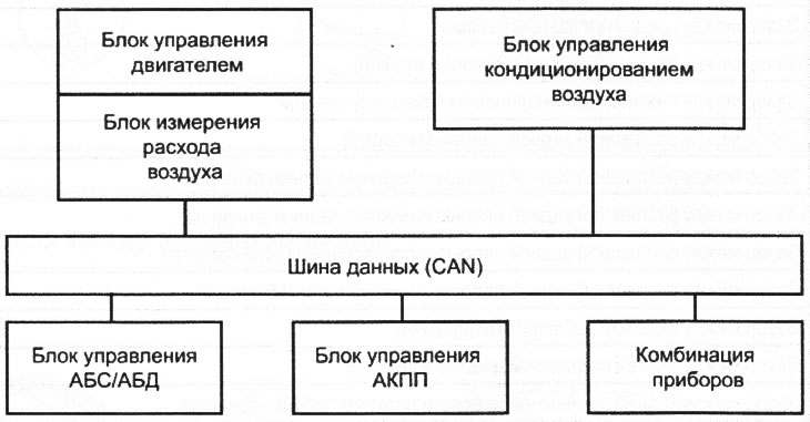
VN 9.001 An exemplary block diagram of a multiplex (CAN) networks