
Cylinder shutdown to reduce fuel consumption
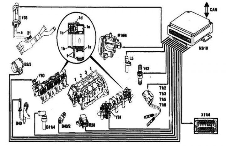
1-8 - Cylinders. Deactivation of cylinders 2, 3, 5 and 8 is possible under certain conditions; 1 - Rocker switch (blocked); 1a - Roller lever; 1b - Valve lever; 1s - Spring; 1d - Connecting pin; 1e - Pressure finger; 21 - Exhaust damper; B2/5 - MAF film type air mass meter; B11 / 4 - Coolant temperature sensor; B28 - Pressure sensor; B40 - Oil level and temperature sensor; B40 / 2 - Oil pressure sensor for shutting off cylinders; Y62 - Injectors for cylinders No. 2, 3, 5 and 8; Y80 - Right-hand cylinder shut-off valve; Y81 - Left cylinder shut-off valve; Y93 - Exhaust plate valve; L5 - Crankshaft position sensor (CKP); M16 / 6 - Throttle actuator; N3/10 - Engine control module (ME-SFI); T1 / 2 - Ignition coil 2; T1 / 3 - Ignition coil 3; T1 / 5 - Ignition coil 5; T1/8 - Ignition coil 8; Х11/4 - Diagnostic connector DLC; a - To the vacuum reservoir; CAN - Data bus
Cylinder shut-off drive
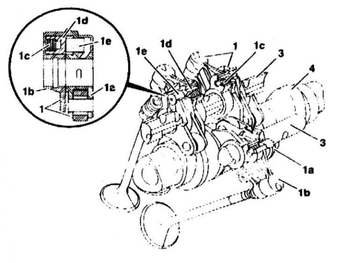
1 - Switching rocker arms; 1a - Roller lever; 1b - Valve lever; 1s - Spring; 1d - Connecting pin; 1e - Pressure finger; 3 - Axes of rocker arms; 4 - Camshaft
 |  |
The valves of cylinders 2 and 3 of the right row are turned off, as well as cylinders 5 and 8 of the left row under certain conditions of the engine operation.
Design/functional principle
To disable cylinders 2 and 3 (right bank of cylinders) and 5 and 8 (left lane) their intake and exhaust valves stop functioning. When the cylinders are turned off, their valves remain permanently closed, fuel injection into them and the supply of explosive voltage to the ignition system are simultaneously stopped.
The shutdown function is organized in the engine control module (ECM):
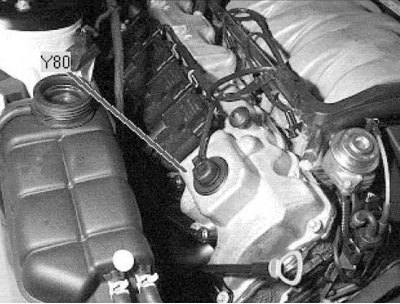
- Shut-off valve activation for right bank cylinders (Y80).
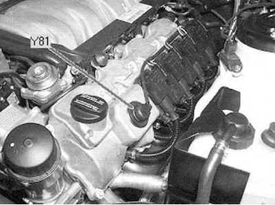
- Shut-off valve activation for left bank cylinders (Y81).
- Exhaust reed valve activation (Y93).
- Cylinder cut-off oil pressure sensor signal (B40/2).
- Pressure sensor signal (B28), absolute pressure in the inlet pipeline.
- Detection of shutdown failures.
Used input signals in the ECM:
- From CKP sensors and engine speed.
- From throttle position sensor (TPS).
- Transmission signal.
- From the oil temperature sensor.
Applicable ECM parameters (ME-SFI) adjusted to the function of deactivating the cylinders. For example:
- Shutting off the fuel supply and supply voltage to certain cylinders, followed by the restructuring of the valve timing and ignition timing under new conditions (cylinders disabled).
- Throttle actuator activation.
- Extrapolation of operating parameters for further changing conditions (cylinders disabled/enabled).
- Adaptation of the composition of the mixture to current changes in air supply and pressure.
- Correction of the STAR diagnostic algorithm.
Cylinder deactivation function deactivated
Both sections of the switchable rocker arm are interlocked with each other by means of a movable connecting pin. The spring presses the pin into the locked position.
Cylinder deactivation function activated
Valves for shutting off the cylinders of the right and left rows (Y80 and Y81) are activated by command from the ECM and open. Oil under pressure is supplied under the pressure finger through the axis of the rocker arms, which leads to pushing back the connecting pins. The rocker sections receive individual degrees of freedom and acquire the ability to move freely relative to each other. The intake and exhaust valves stop functioning.
The undocked valve lever rests on the heel of the cam, which ensures that the sliding locking pin enters the roller cam seat to override the cylinder deactivation function.
Working moments of the procedure for deactivating the cylinders
Due to design features, cylinder deactivation can only be implemented in certain engine positions:
- The valves must be closed. Operation becomes possible only when the rocker arms are unloaded.
- At the end of the work cycle, the exhaust valves are always turned off first, the inlet valves are the last. In this case, gas under pressure enters the switch-off cylinder. The pressure prevents oil from being drawn out of the crankcase. The lambda control remains disabled when the cylinders are further turned on and the exhaust gases are released.
- First, cylinders 2 and 3 of the right row are turned off, then 8 and 5 of the left (in the order listed).
Cylinder Deactivation Activation Status
- Shutdown period (about 20 seconds) expires after starting the engine.
- Engine coolant temperature is higher than +20°C.
- Engine speed at normal operating temperature is:
- 925 ÷ 1700 per minute with 3rd gear engaged.
- 925 ÷ 1700 per minute with 4th gear engaged.
- 925 ÷ 3500 per minute with 5th gear engaged.
- AT mode: 3, 4 or D.
- The throttle opening angle does not exceed the threshold value determined by engine requests.
- Oil pressure exceeds 2.5 atm.
- The engine oil temperature is within the range of 20 ÷ 130°C.
- The intake air temperature is about -40 ÷ 100°C.
- The height of the place does not exceed 2500 m above sea level.
- The battery output voltage is at least 10.5V.
- Cylinder deactivation occurs for the STAR diagnostic coding variant.
- Traction control system controller (ASR) not activated.
State of deactivation of the cylinder deactivation function
- Harmful to the 3-functional catalytic converter are detected (TWC) misfiring.
- A violation of the cylinder shutdown function has been detected.
- Accelerator electronic control emergency mode activated
- An oil temperature sensor signal failure has occurred.
- An oil pressure sensor signal has failed.
- On demand of the functional circuit diagnostic device.
- There is an excessive violation of the stability of revolutions for the conditions of the disabled state of the cylinders.
- Maximum allowable continuous operation time exceeded (about 25 seconds).
The cylinder deactivation function will be activated again after about 20 seconds.
Threshold for activation of the cylinder deactivation function
The activation threshold determines the conditions for deactivating and enabling the cylinder deactivation function at medium crankshaft speed and moderate engine load and depends on the correct programming of the STAR diagnostic parameters. The following program adjustments are allowed:
- The threshold is selected from the basic settings of the engine output parameters
- A restriction is introduced on activation at revolutions below 1500 per minute.
- A restriction is introduced on the current state of the engine output parameters.
- The shutdown function is deactivated.
Note. When the cylinder deactivation function is activated, only temporary adjustments to the STAR diagnostic parameters are allowed to restore disturbed comfort. It should be remembered that the introduction of restrictions on the shutdown of cylinders negatively affects fuel consumption.
Throttle actuator activation
When the function is activated, 4 cylinders of the engine are disabled. At the same time, the torque is kept as constant as possible. The throttle valve opens again, depending on the load and engine speed. When the cylinders are turned off, the reverse is activated and the throttle valve closes accordingly.
The throttle valve is briefly activated before the activation and deactivation of the cylinder deactivation function.
When switching between two modes of operation of the engine, the same torque should be developed, if possible, in order to eliminate a noticeable difference in the power developed by the engine and achieve smooth switching.
Exhaust flap activation
When the cylinder deactivation function is activated, the exhaust flap solenoid valve is actuated by the ECM (ME-SFI) at engine speeds up to 2500 per minute. A vacuum is applied to the diaphragm of the actuator and the damper partially covers the cross section of the exhaust pipe, which reduces the background noise level.
Activation of cylinder shut-off valves
Valves for shutting off the cylinders of the right and left rows (Y80 and Y81) are activated by a voltage pulse signal issued directly by the engine control module (ME-SFI).
With the cylinder shutdown function activated, the switching speed reaches 95% for approximately 0.5 seconds in order to increase the starting current and improve the response speed. The coil windings are protected from thermal overload by introducing a time limit.
Additional measures applied on the power unit when the cylinders are turned off
- Selected high performance oil pump (as on the engine 120).
- A vibration damper is installed on the belt drive.
- In order to reduce background noise, a rotation converter with a turbine torsional damper is used.