
Fuel tank
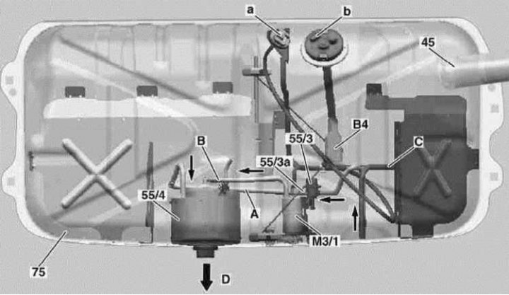
45 - Filler neck; 55/3 - Fuel pressure regulator (5.3 atm.); 55/3a - Damper (50 liters per hour); 55/4 - Intake chamber; 75 - Fuel tank; B4 - Fuel level sensor; M3/1 - Pump built into the fuel tank; A - Connector for the electrical wiring of the pump built into the fuel tank; B - Fuel level sensor wiring connector; A - Fuel return from pressure regulator (5.0 atm.) into the spray chamber; B - Line for filling the intake chamber from a pump built into the fuel tank; C - Fuel tank ventilation line; D - To fuel pump
Functional diagram of the microprocessor control system ME SFI 2.0. V6 and V8 engines
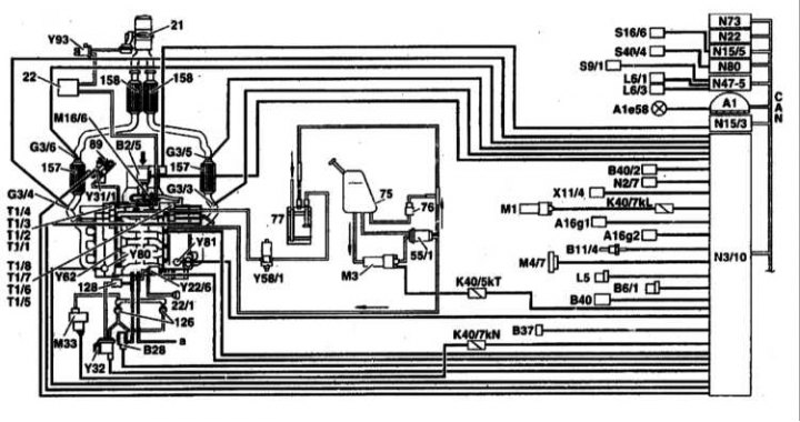
Shown with engine 113 as an example
21 - Exhaust damper1; 22 - Vacuum reservoir1; 22/1 - Intake manifold diaphragm switch; 55/1 - Fuel filter with integrated pressure regulator; 75 - Fuel tank; 76 - Ventilation valve; 77 - Coal adsorber; 89 - EGR valve; 126 - Secondary air mixing off valve (combustion chamber valve: built-in non-return valve); 128 - Non-return vacuum valve; 157 - Three-function catalytic converter at the bulkhead of the engine compartment; 158 - Three-function catalytic converter under the bottom; a - Other consumers; A1 - Dashboard; A1e58 - Control lamp for diagnosing engine failures; A16g1 - Knock sensor 1 (right side of the engine); A16g2 - Knock sensor 2 (left side of engine); B2/5 - Film sensor for measuring air mass (MAF) (integrated intake air temperature sensor [IAT]); B6 / 1 - Camshaft Hall effect sensor; B11 / 4 - Coolant temperature sensor (CTS); B28 - Pressure sensor1; B37 - Pedal position sensor; B40 - Level / temperature / oil quality sensor; B40 / 2 - Oil pressure sensor for cylinder shut-off system1; G3/3 - Left (upper flow) oxygen sensor; G3/4 - Right (upper flow) oxygen sensor; G3/5 - Left (downstream) oxygen sensor; G3/6 - Right (downstream) oxygen sensor; K40/5kT - Fuel pump relay; K40/7kL - Starter relay; K40/7kN - Secondary air mixing system relay; L5 - Crankshaft position sensor (CKP); L6 / 1 - Left front wheel sensor; L6 / 3 - Left rear wheel sensor; M1 - Terminal 50 starter; M3 - Fuel pump; M16 / 6 - Throttle actuator; M33 - Electric air pump; N3/10 - ECM (ME-SFI); N15/3 - Electronic traction control control module (ETC); N19 - Auxiliary air control push button control module (AAS); N22 - Auxiliary air control push button control module (AAS); N47-1 - Traction control system control module (ASR) / speed-sensitive power steering system (SPS); N54-1 - IR DAS control module; S16 / 10 - Switch for determining the position of the transmission; S40/4 - Tempostat variable speed switch; T1 / 1 -; Т1/8 - Ignition coils of cylinders 1-8 (twin coils); Х11/22 - Diagnostic socket DLC II; Y22 / 6 - Valve-switch of the inlet pipeline of variable length of the path; Y31/1 - EGR vacuum transducer; Y32 - Valve-switch of the air pump of the secondary air mixing system (AIR); Y58/1 - Canister purge control valve; Y62 - Fuel injection injectors; Y80 - Right bank cylinder deactivation valve1; Y81 - Left bank cylinder deactivation valve1; Y93 - Exhaust flap1; CAN - Data bus.
1 Only engine 113.960 with cylinder deactivation (code 479)
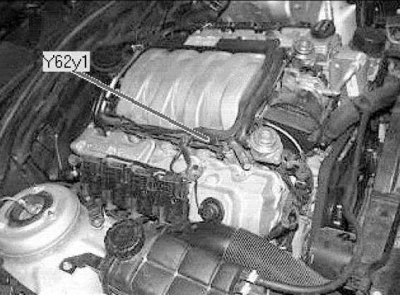
Location of some electrical components
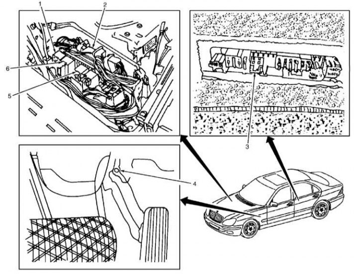
1 - Relay for electronic control systems of the engine and running gear; 2 - ECM (ME-SFI); 3 - Fuel pump relay; 4 - Pedal pressure sensor; 5 - Air pump relay; 6 - Starter relay
Variable geometry intake airflow
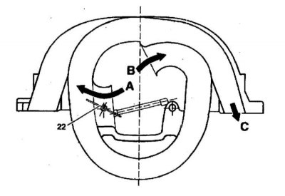
A - Air flow with the control damper open at engine speeds over 3900 rpm; 22 - Control damper (one for each cylinder); B - Air flow with the damper closed, at low loads in the 1750-3900 rpm range; C - To the engine
Gas distribution management. V6 and V8 engines
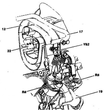
12 - Inlet pipeline; 17 - Fuel distribution line; 19 - Exhaust manifold with air gap insulation; 22 - Resonant damper; R4 - Spark plugs (2 per cylinder); Y62 - Injector
Elements of the inlet pipeline with variable geometry
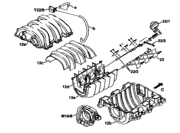
12a - The upper part of the pipeline; 12b - The lower part of the pipeline; 12c - Upper part of the pipeline insert; 12d - Lower part of the pipeline insert; 22 - Control damper; 22/1 - Diaphragm assembly for switching the pipeline; 22/2 - Damper axles; 22/3 - Connecting rods; a - Tube to the diaphragm assembly; b - Tube to pipeline changeover valve; M16 / 6 - Throttle actuator; Y22/6 - Inlet pipeline
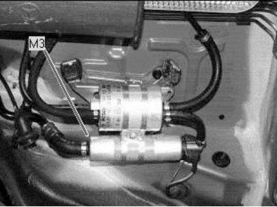
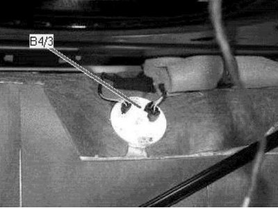
Fuel pump assembly (under the bottom, left rear)
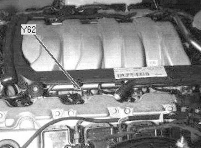
fuel injectors (sides of the engine)
Fuel tank pressure sensor (front center trunk)
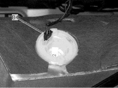
Fuel gauge (front center trunk)
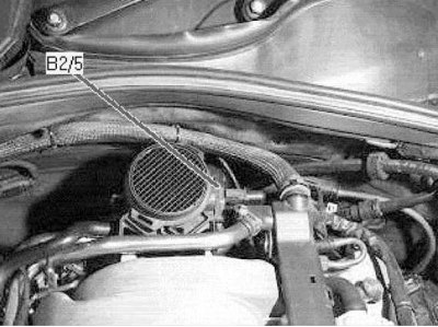
Intake air thermometer (center back of engine)
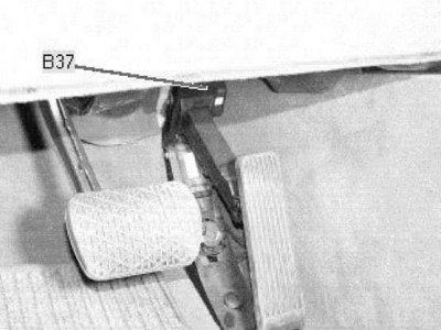
Accelerator pedal sensor
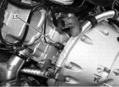
crankshaft position sensor
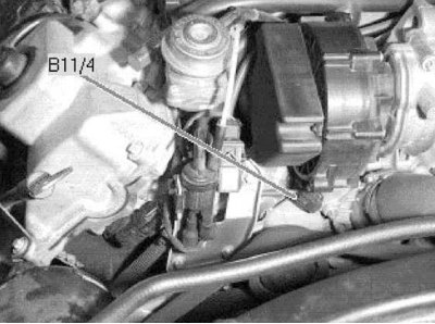
coolant temperature sensor (front, center of engine)
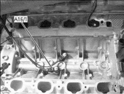
knock sensors
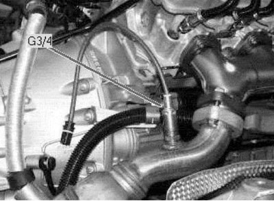
Right pre-catalytic lambda probe
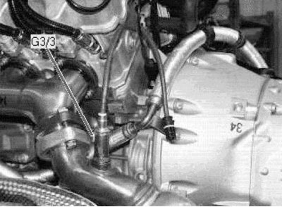
Left pre-catalytic lambda probe
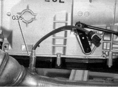
Left post catalytic lambda probe
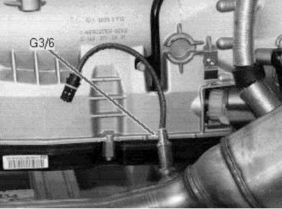
Right post-catalytic lambda probe
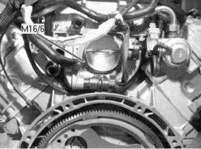
Throttle valve setting element (center back of engine)
Fuel injection injector in the 1st cylinder (right side of the engine)
Gasoline engines
The composition of the fuel system includes: installed at the rear of the car (under the rear seat cushion) fuel tank with activated charcoal adsorber, fuel lines, electric fuel pump, and electronic sequential injection system controlled by the control unit. The functional diagram of the control system and the location of the sensors are shown in the accompanying illustrations.
The fuel reserve is shown to the driver on the instrument panel. In a gasoline engine, gasoline vapors are collected in an adsorber and fed into the combustion chambers of the engine.
Driving style has a significant impact on fuel consumption. Tips for reducing fuel consumption:
- Drive away immediately after starting the engine, even if it is in the cold.
- When the vehicle is stopped for more than 40 seconds, turn off the engine.
- Always drive in the highest possible gear.
- When driving long distances, maintain a steady speed whenever possible. Avoid driving at high speeds. Drive carefully. Don't slow down unnecessarily.
- Do not transport excess cargo on the vehicle. If the roof rack is not in use, remove it from the roof.
- Check tire pressure. Avoid excessive pressure reduction.
Diesel engines
The composition of the fuel system includes: installed at the rear of the car (under the rear seat cushion) fuel tank, fuel filter, injectors, fuel pipes and hoses, a fuel gauge located inside the tank and an electronic engine control unit.
Fuel is supplied by a special pump through the filter. Dirt and water contained in the fuel settles in the filter.
The engine is controlled by an electronic system similar to that of a gasoline engine. The system controls the operation of the engine by analyzing information from a large number of sensors.
Diesel models do not have an accelerator cable. Instead, a pedal position sensor is installed on the pedal.
There is no fuel cut-off valve when the ignition is turned off. In order to turn off the engine when the ignition is turned off, the engine control unit sends a signal to the injection pump control unit, which, in turn, stops the fuel supply to the injectors.
The fuel tank components are not removable. The fuel system is designed to prevent «suction» air without fuel in the tank. The control unit constantly checks the fuel level in the tank, processing information from the fuel reserve sensor located in the tank. When the fuel supply drops to a certain level, the control unit lights up a warning lamp on the dashboard, after which it forcibly causes fuel skips, thereby limiting the maximum speed. This continues until the level of fuel in the tank exceeds the allowable mark.
The fuel system of diesel engines is very reliable. When using clean fuel and performing regular maintenance, it should function properly until the end of the vehicle's life. After very long mileage, the internal components of the injectors may wear out and need to be repaired. Since the pump - nozzles are of a complex design, repairs are recommended to be carried out in a specialized workshop.
Fuel pump draws fuel (D) from the bottom of the damper (55/4), which serves to prevent air from entering the inlet tract of the pump during cornering with a low level of fuel in the tank (75).
Submersible fuel pump (M3/1) controlled by an electronic module that monitors the quality of the damper filling and provides a flow rate of 220 l / h with an effective pressure of 0.3 atm.
Additionally, fuel is pumped into the damper by an auxiliary suction pump, which operates due to the flow of excess fuel returned to the tank from the pressure regulator (5.0 atm.).
Components placed inside the tank (including fuel pump) they are not subject to removal and refurbishment, and in case of their failure, the entire tank assembly is subject to replacement. The only exception is the fuel gauge (AT 4).
Throttle (55/3a) reduces fuel consumption in the return line connected to the booster pump (A) up to 50 l/h at a pressure of 5.0 atm. The pressure regulator prevents an increase in pressure over 5.3 atm.
Safety precautions and cleanliness when working with the fuel system
The following safety and cleanliness precautions must be observed when working on the fuel system:
Safety note
Do not use open flames near the workplace, do not smoke or hold any objects that are very hot. There is a danger of an accident! Keep a fire extinguisher ready.
Keep the workplace well ventilated. Fuel vapors are poisonous.
The fuel system is under pressure. When the system is opened, fuel can escape under pressure. Collect the fuel with a rag. Wear protective goggles.
Take special precautions when working on diesel engine power system components. This is especially true for injectors. Keep in mind that the fuel pressure at the outlet of the injectors is about 1100 atmospheres. Do not expose any part of the body to the jet of fuel.
Hose connections are fastened with tape or clamp clamps. Clamp clamps must always be replaced with band clamps or clamps of the latest design. A special tool is available for the installation of band clamps, eg HAZET 796-5.
Thoroughly clean connections and adjacent areas before opening.
Place the removed parts on a clean lining and close. Use polyethylene or paper for this. Do not use fiber cloth for this!
Carefully cover open parts or install technological plugs if the repair will last for some time.
Replace only clean parts. Remove spare parts from the packaging only immediately before installation. Do not use parts that have been stored unpackaged (e.g. stored in a toolbox).
With an open fuel system, if possible, do not work with compressed air. If possible, do not move the vehicle while doing this.
Do not use sealants containing silicone. The silicone elements in the engine that got into the engine do not burn out and damage the oxygen sensor.
Safety measures when removing the fuel tank:
- Before removing the tank, drain the fuel from it or pump out the fuel with a pump specially designed for this purpose.
- The fuel tank is removed from the underside of the vehicle. Before disconnecting the tank mounting clamps, bring a jack and linings to it from below.
- An empty tank is explosive and cannot be disposed of in this form. Before disposal, the tank must be cut into pieces. Be careful not to create a spark. To do this, hand over the fuel tank to a specialized company.
- After installing the tank in place, start the engine and check the tightness of all connections.