



Air blower design
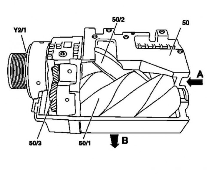
50 - Air blower; 50/1 - Spiral shaft 1; 50/2 - Spiral shaft 2; 50/3 - Gear transmission; Y2/1 - Electromagnetic clutch of the air blower; A - Suction side opening; B - Discharge side opening (bottom of the body)
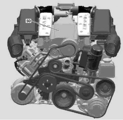
Air blower
The design and layout of the belt-driven air blower are shown in the illustrations.
Air is supplied to the working chamber of the supercharger through the opening on the side (A).
Thanks to the rotation and geometry of the two spiral shafts (50/1, 50/2) the working chamber is separated from the incoming air flow. The air is compressed. Due to further rotation, the compressed air is pushed through the opening B from the discharge side to the intercooler.
(Article was borrowed from the website mercedesman)
The maximum pressure increase is about 1.1 atm. on M112K and about 0.8 atm. on M113K at maximum engine speed.
The supercharger is driven directly from the crankshaft via an electromagnetic clutch (Y2/1) and a separate ribbed belt.