
Elements of toxicity reduction systems
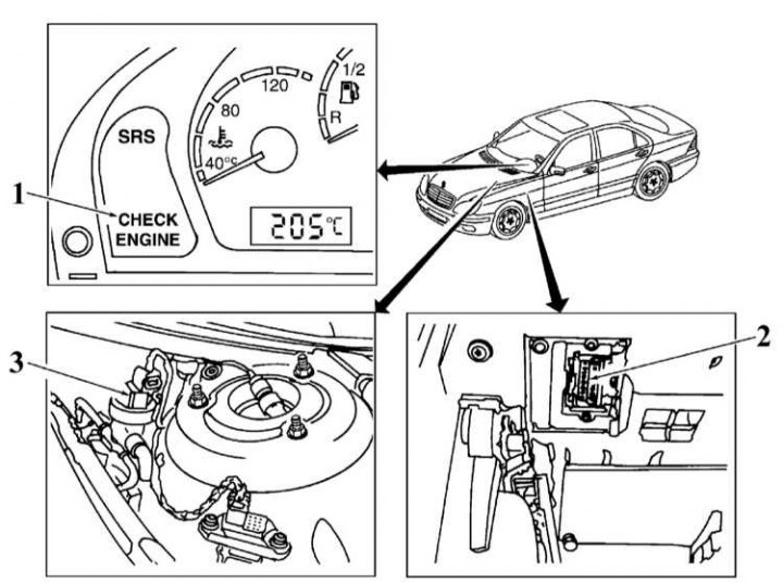
1 - Control lamp «Check engine»; 2 - Diagnostic connector; 3 - Carbon adsorber purge valve
Scheme of laying vacuum lines. V6 and V8 engines (112, 113)
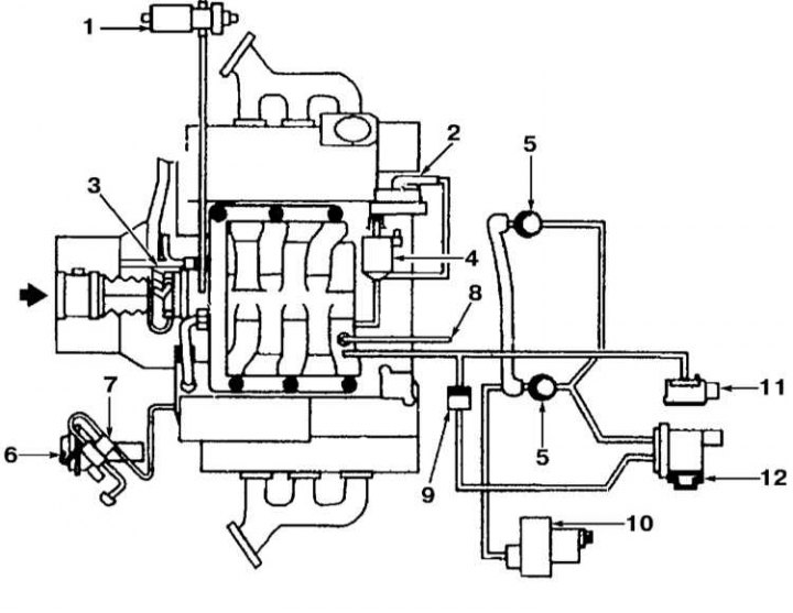
1 - Adsorber purge valve; 2 - Diaphragm device for switching the intake pipeline; 3 - Throttle actuator; 4 - Resonant intake manifold switching valve; 5 - Shut-off valve for mixing air into the exhaust with a built-in control valve; 6 - Exhaust gas recirculation valve (EGR); 7 - Vacuum transmitter of the EGR system; 8 - To other vacuum consumers; 9 - Vacuum control valve; 10 - Electric vacuum pump; 11 - Pressure sensor; 12 - Air pump switching valve
Location of elements of toxicity reduction systems
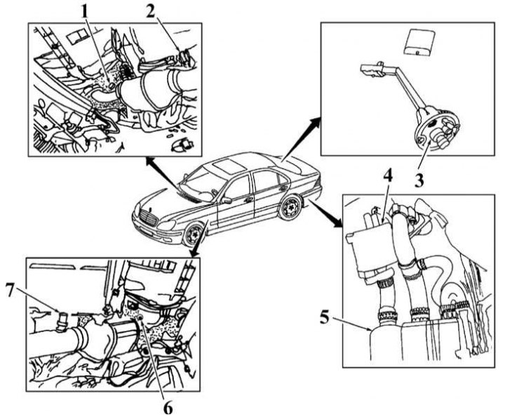
1 - Right pre-catalytic lambda probe 1; 2 - Right post-catalytic lambda probe 2; 3 - Pressure sensor in the fuel tank; 4 - Adsorber purge valve; 5 - Adsorber of the fuel vapor recovery system; 6 - Left pre-catalytic lambda probe 1; 7 - Left post-catalytic lambda probe 2
Functional diagram of the fuel vapor recovery system
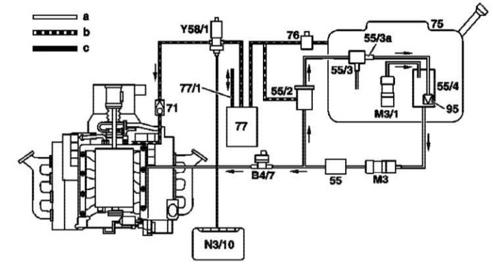
55 - Fuel filter; 55/2 - Fuel pressure regulator 5.0 atm.; 55/3 - Fuel pressure regulator 5.3 atm.; 55/3a - Damper; 55/4 - Spray chamber; 71 - Valve; 75 - Fuel tank; 76 - Ventilation valve; 77 - Coal adsorber; 77/1 - Pressure / vacuum line; 95 - Pump for pumping out the mixture; B4/7 - Fuel pressure sensor; M3 - Fuel pump; M3/1 - Pump built into the fuel tank; N3/10 - Electronics control unit for phased fuel injection (ME-SFI); Y58/1 - Canister purge control valve; a - Fuel line; b - Purge line; c - Wiring
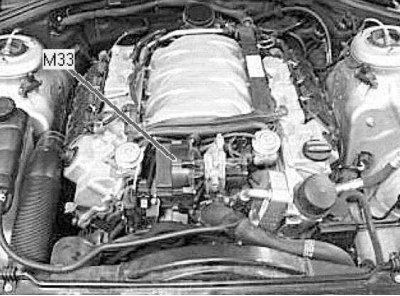
Exhaust air injection electric pump
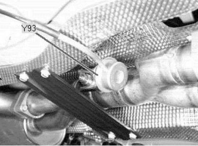
Exhaust flap valve (under the bottom)
Exhaust air pump switching valve (engine front)
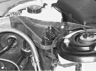
Canister purge control valve (left rear of the engine compartment)
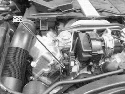
EGR Valve Vacuum Transmitter (rear of engine)
Petrol models
All petrol models must use unleaded petrol only. The engine management system operates in such a way as to get the most out of the engine while minimizing fuel consumption and exhaust emissions. The vapor recovery system prevents fuel vapor from entering the atmosphere from the fuel tank. An exhaust gas recirculation system was installed.
Crankcase ventilation system
To eliminate leakage of unburned hydrocarbons into the atmosphere, the engine is completely sealed. Gases and oil vapors formed in the crankcase enter the intake manifold through a strainer and burn in the cylinders along with the fuel.
Gases are removed from the crankcase due to the pressure difference in the crankcase and inlet pipeline (pressure in the crankcase is higher).
Reducing the toxicity of exhaust gases
To reduce the amount of harmful emissions into the atmosphere on all gasoline models, a three-function catalytic converter is integrated into the exhaust system. The fuel injection control system has feedback, which includes an oxygen sensor. This sensor, installed in the exhaust system, constantly informs the control unit about the composition of the exhaust gases. Depending on the received data, the control unit corrects the quality of the mixture supplied to the combustion chambers and, thus, optimizes the combustion of the fuel.
A heating element is built into the lambda probe, which is switched on by the control unit through a special relay. The working surface of the lambda probe is sensitive to changes in the oxygen content in gases. Depending on the oxygen concentration, the sensor sends signals of different voltages. If the mixture is too rich - the oxygen content in the exhaust gases is very low, the sensor gives low voltage signals. The voltage increases as the mixture becomes leaner and the oxygen content of the gases increases. The converter works most efficiently with the optimal composition of the combustible mixture (14.7 parts of air to 1 part of fuel). At the optimum concentration of oxygen in the exhaust gases, a jump in voltage occurs on the sensor. This jump is the starting point for the control unit when adjusting the quality of the mixture.
Two sensors are installed. One is before, and the second is after the converter. This achieves a more accurate monitoring of the composition of the exhaust gases.
Exhaust gas recirculation system
The exhaust gas recirculation system helps to reduce the amount of NOx in the exhaust gases. To do this, a small part of the exhaust gases is fed into the intake manifold through a special valve. The valve of the recirculation system is controlled by the control unit.
Evaporative Emission System
To reduce the emission of unburned hydrocarbons into the atmosphere, a fuel recovery system is installed on all gasoline models. The filler neck of the fuel tank is hermetically sealed with a lid, a carbon adsorber is installed under the fuel tank. It collects fuel vapors that form in the tank while the car is parked and is stored there until the filter purge begins at the signal of the control unit. Then fuel vapors begin to flow through the purge valve (Y58/1) into the intake manifold, where they are mixed with the working mixture and then burned in the usual way in the combustion chambers.
To ensure normal operation of the engine at idle and during warm-up, the control unit keeps the valve closed. This prevents unburned fuel from entering the converter (mixture is too rich at high idle). After the engine warms up, the valve begins to open and close, supplying fuel vapor to the intake tract.
A check valve in the purge line prevents pressure build-up in the adsorber. Canister purge is activated in the following cases:
- coolant temperature is more than 70°С;
- the engine runs longer than 2 minutes;
- not when coasting;
- lambda probe is not active.
The purge force is controlled by the control unit. The adsorber replenishment amount is determined by the different switch-on times with constant opening and closing of the valve. Variations in crankshaft speed during scavenging are prevented by idle control.
When the fuel tank cap is open, the vent valve does not open, causing the outlet to close faster and preventing fuel from entering the canister.
Diesel models
The engine management system operates in such a way as to get the most out of the engine while minimizing fuel consumption and exhaust emissions. To further reduce the toxicity of gases, several additional systems are installed on the car. The crankcase ventilation system reduces gas leakage to the atmosphere from the engine lubrication system. The catalytic converter reduces the toxicity of exhaust gases. An exhaust gas recirculation system was installed.
Controlled crankcase ventilation system
To eliminate leakage of unburned hydrocarbons into the atmosphere, the engine is completely sealed. Gases and oil vapors formed in the crankcase enter the intake manifold through a strainer and burn in the cylinders along with the fuel.
Gases are removed from the crankcase due to the pressure difference in the crankcase and inlet pipeline (pressure in the crankcase is higher). All diesel models are equipped with a ventilation valve. It is located on the head cover and controls the flow of gases from the crankcase.
Catalytic converter
To reduce the amount of harmful emissions into the atmosphere on all diesel models, a catalytic converter is integrated into the exhaust system. It neutralizes most of the gaseous hydrocarbons, CO and other harmful impurities that make up the exhaust gases.
Exhaust gas recirculation system
All diesel models also have an exhaust gas recirculation system. This system reduces the amount of NOx in the exhaust gases. To do this, a small part of the exhaust gases is fed into the intake manifold through a special valve. The valve of the recirculation system is controlled by the control unit.