
Glow plugs consist of a threaded body and a heating element built into the body.
When the glow plug is turned on, a current of 30 A flows through it. At the same time, the heating coil heats up the candle. The control coil during heating limits the current to 15-25 A and limits the heating temperature of the candle, which helps to increase the service life of the candles.
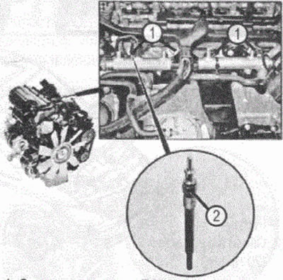
VN 9.036 1. Glow plugs R9; 2. Glow plug 1st cylinder R9/1
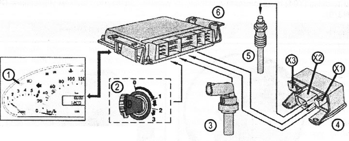
VN 9.037 Glow plug heating system; 1. Indicator lamp for preheating glow plugs A1e16; 2. Ignition lock switch; Ignition key positions:; 0. The key can only be removed from the keyhole in position; 1. Most electricity consumers are on; 2. Position of preheating and driving mode; 3. Starter engagement position; 3. Coolant temperature sensor B11/4; 4. Glow plug output stage connector N14/2; 5. Glow plugs R9; 6. Engine control unit N3/9; X1. Pin 1 of connector 14/2: output of information about the inclusion of preheating to the engine control unit (Feedback); X2. Pin 2 of connector 14/2: power supply for glow plugs; HZ. Pin 3 of connector 14/2: battery powered circuit 30
Placement and connection of glow plugs in the engine
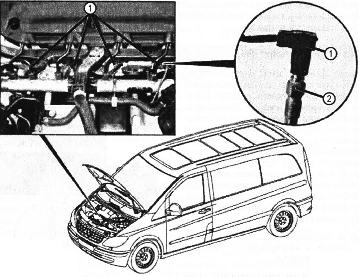
VN 9.038 1. connector; 2. Glow plugs (20 Nm) R9