



Contents: Removal ↡ Installation ↡
Removal
1. Remove the crankshaft.
2. Fix the cylinder block 1 to the boring machine 3 (figure 3.20a).
3. Align the cylinder liner with the boring of the machine 3.
4. Fix the boring and bore sleeve 2 to half the thickness in several steps. If multiple liners are being replaced, be careful when performing the boring operation and perform it in a 2-4-1-3 order to avoid excessive temperature effects.
5. Bore sleeve 2 to 0.2 mm less than the outside diameter.
6. Remove the sleeve 2
Installation
7. Measure the diameter of cylinder 1 (figure 3.20b).
8. Lubricate the cylinder with a non-alcohol based lubricant.
9. Measure the sleeve 2 (figure 3.20c).
10. Install cylinder block 1 on the press.
11. Install sleeve 2 into the hole at the correct angle.
12. Press in sleeve 2 so that it protrudes 20 mm above the cylinder block.
13. Press in sleeve 2 until it stops.
14. Grind the contact surface of the cylinder block 1.
15. Fix cylinder block 1 on the boring machine.
16. Boring the cylinder bore in several steps. Recommended rotation speed: 250-280 rpm. Feed rate: 0.04-0.06 mm/rev. The cylinder block dimensions are given in Table 3.8.
17. Hone the cylinder bore to the desired result. Working pressure: 2.5-3.0 bar. Rotation speed: 60-100 rpm. Honing angle: 40-60°. Number of cycles: 30-40.
18. Measure adjacent sleeves and hone them if necessary.
19. Wipe cylinder block 1.
20. Apply marks to surfaces 3 on the cylinder block after repair. Tags (classification) cylinders and cylinder block heights (distance A) are applied to surfaces I and II on the cylinder block (figure 3.20g). On 904 engines there are three marks: I - on cylinders 1-3 and mark II - on cylinder 4. Each repair of cylinder block 3 must be noted in these fields.
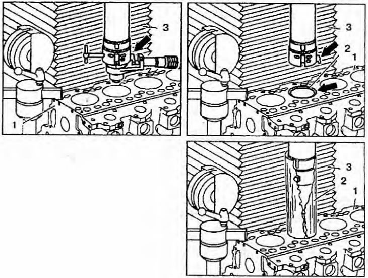
Figure 3.20a. Removing the cylinder block sleeve: 1 - Cylinder block; 2 - Sleeve; 3 - Boring tool.
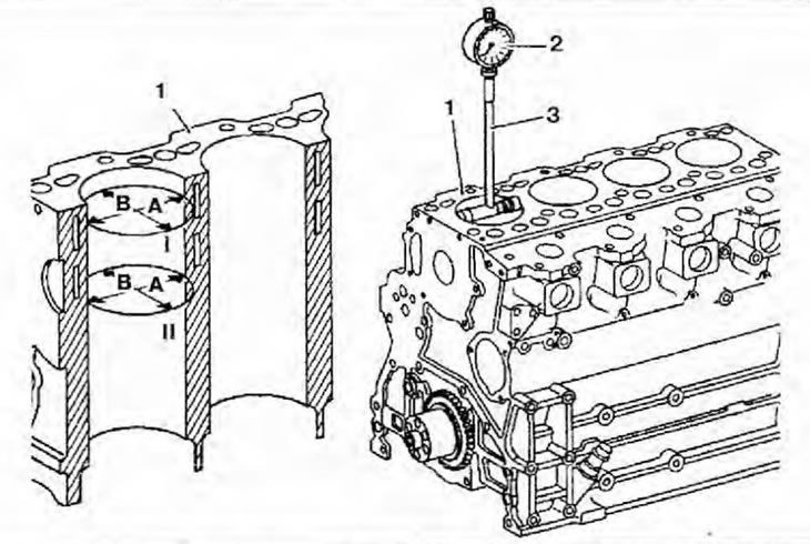
Figure 3.20b. Measuring the cylinder diameter: 1 - Cylinder block; 2 - Indicator; 3 - Bore gauge; A, B - Directions of measurements; I - Measurement at TDC; II - Measurement in the middle of the cylinder.
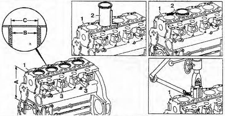
Figure 3.20c. Installing the cylinder block sleeve: 1 - Cylinder block; 2 - Sleeve: 3 - Marking surfaces of the cylinder block; A - Cylinder block height; B - Sleeve diameter; C - Sleeve cuff diameter.
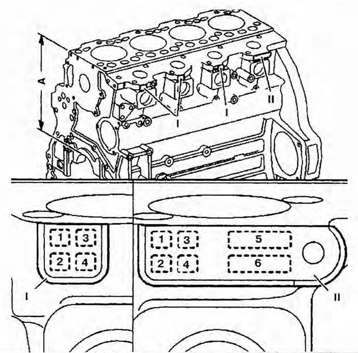
Figure 3.20g. Marking surfaces of the cylinder block.
Table 3.8. Cylinder block dimensions
| Parameters | Engines 904.9 | |
| Inner diameter of cylinder or sleeve, mm | Code A | 101.985-101.991 |
| Code B | 101.992-102.008 | |
| Code C | 102.009-102.015 | |
| Outer diameter of the sleeve, mm | 106.075-106.095 | |
| Roughness Rz of the cylinder wall or liner, µm | 2.5-4.5 | |
| Height of cylinder block A, measured from the main bearing seat to the mating surface of the cylinder head, mm | Standard | 298.35-298.50 |
| Rem. size -0.3 | 298.05-298.20 | |
| Rem. size -0.6 | 297.75-297.90 | |
| Rem. size -0.9 | 297.45-297.60 | |
| Diameter B of the hole in the cylinder block for the liner, mm | 106.000-106.035 | |
| Diameter of the cuff in the cylinder block under the liner, mm | 109.572-109.626 | |
| Roughness Rz of the mating surface of the cylinder block, mm | 8-16 | |
Read more on the website [MERCEDESMAN]