



Contents: Removal ↡ Installation ↡
Removal
1. Remove the cylinder head.
2. Remove the tray.
3. Remove the connecting rod cap 5 (figure 3.16a).
4. Remove piston 1 together with connecting rod 4 from the cylinder block.
5. Mark the liners 7 together with the connecting rod caps 5 and connecting rods 4.
6. Remove piston pin 2 and remove connecting rod 4.
7. Check the connecting rod bolts 6.
8. Check the pistons and cylinder walls for wear. The piston dimensions are given in Table 3.5.
[Information copied from the website www.mercedesman.ru]
9. Check the piston rings, replace damaged ones.
10 Check and measure the dimensions of connecting rods 4 and 5 and connecting rod bearings 7.
Table 3.5. Piston dimensions
| Parameters | Engines 904 | ||
| Piston diameter, mm | BA label | 101.781-101.790 | |
| BC Label | 101.790-101.799 | ||
| Distance from the bottom of the piston to the axis of 1 piston pin | Standard | 102 BA | 64.36-64.40 |
| 102BC | |||
| Rem. size 1 | 102VA -0.3 | 64.06-64.10 | |
| 102BC -0.3 | |||
| Rem. size 2 | 102VA -0.6 | 63.76-63.80 | |
| 102BC -0.6 | |||
| Rem. size 3 | 102VA -0.9 | 63.46-63.50 | |
| 102BC -0.9 | |||
| Piston protrusion above cylinder block, mm | 0.28-0.50 | ||
Installation
11. Assemble piston 1 and connecting rod 4 together.
12. Lubricate piston 1 and install piston ring locks at 120° (arrow) (figure 3.166).
13. Install tension band 9 on the piston and tighten it to piston diameter 1.
14. Install the bearing shell 7 on the connecting rod 4 and the oil contact surface.
15. Insert piston 1 into the cylinder block so that the tension band touches the cylinder block. The arrow on the piston should point towards the front of the vehicle.
16. Push piston 1 into the cylinder block.
17. Tighten bolts 6 securing connecting rod cover 5.
18. Measure the piston protrusion.
19. Install the tray.
20. Install the cylinder head.
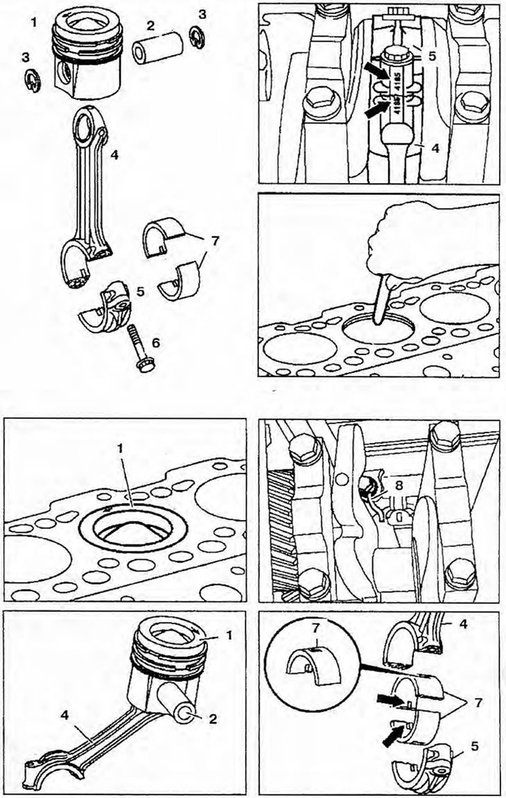
Figure 3.16a. Pistons: 1 - Piston; 2 - Piston pin; 3 - Retaining rings; 4 - Connecting rod; 5-Connecting rod cover; 6 - Connecting rod bolt; 7 - Connecting rod bearings; 8 - Oil nozzle.
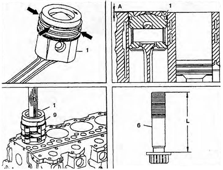
Figure 3.16b. Pistons: 1 - Piston; 6 - Length of connecting rod bolt; 9 - Tension tape; A - Piston protrusion.