



Removal
1. Remove the pistons.
Examination
2. Check the connecting rods for wear. Connecting rods with blue color should be replaced.
3. Check the inner diameter of the bushing 5 of the upper connecting rod head (figure 3.18).
4. Check connecting rod 1 for distortion and deviations from acceptable dimensions. The connecting rod dimensions are given in Table 3.6.
5. Install the connecting rod bearings 3 and measure the diameter.
6. Measure the axial clearance of the connecting rod bearings.
Installation
7. Install the pistons.
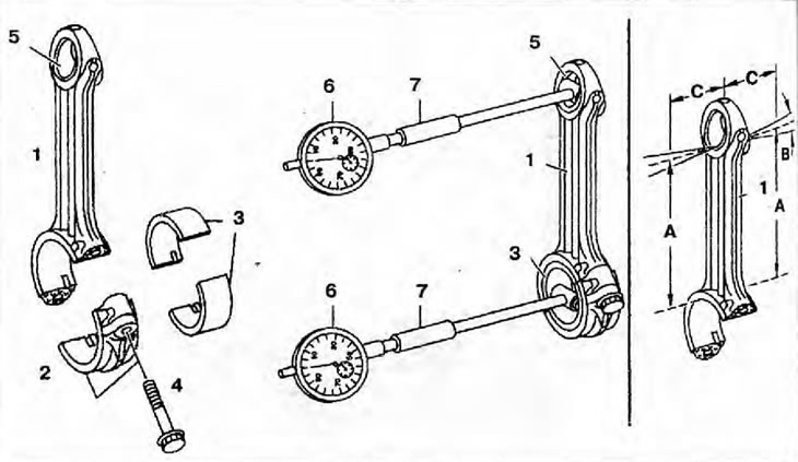
Figure 3.18. Connecting rods: 1 - Connecting rod; 2 - Connecting rod cover; 3 - Connecting rod bearings; 4 - Connecting rod bolts: 5 - Connecting rod upper head bushing; 6 - Indicator; 7 - Support; A - Distance between upper and lower connecting rod heads; B - Permissible change in axial parallelism between the upper and lower heads of the connecting rod in relation to the measured value; C - Measured distance.
Table 3.6. Connecting rod dimensions
| Parameters | Engines up to number 119308 | Engines starting from number 119309 | |
| Inner diameter of the lower connecting rod head with installed liners, mm | Standard | 70.054-70.093 | |
| Rem. size 0.1 | 69.954-69.933 | ||
| Rem. size 0.25 | 69.804-69.843 | ||
| Rem. size 0.5 | 69.554-69.593 | ||
| Rem. size 0.75 | 69.304-69.343 | ||
| Rem. size 1.0 | 69.054-69.093 | ||
| Diameter of the lower connecting rod head without liners, mm | 75.000-75.019 | ||
| Permissible change in axial parallelism between the upper and lower heads of the connecting rod in relation to the length of more than 50 mm, mm | 0.025 | ||
| Connecting rod bearing clearance, mm | Radial | 0.039-0.098 | |
| Axial | 0.170-0470 | ||
| Permissible ovality of holes, mm | Connecting rod upper head bushing | 0.006 | |
| Lower connecting rod head | 0.008 | ||
| Inner diameter of connecting rod upper head bushing, mm | 40.03-40.04 | 42.03-42,04 | |