



2. Select the adjustment method (they are described below): Method 1 - Adjustment by the order of cylinder firing; method 2 - adjustment at two positions of the crankshaft.
3. Attach the rotating device 4 to the hole in the timing cover and set the crankshaft to the position corresponding to the adjustment method (figure 3.11a).
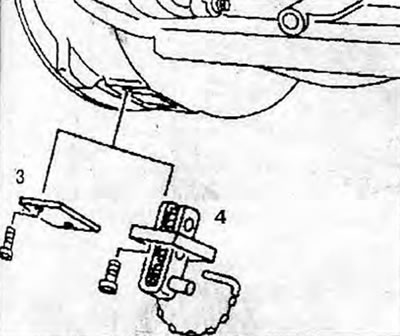
Figure 3.11a. Remove cover 3 and attach rotating device 4 to the hole in the timing belt cover.
4. Press switch S11 and then switch S10, and set the crankshaft to the position corresponding to the adjustment method (figure 3.11b). The engine will not start unless the engine is started and the switches are pressed simultaneously.
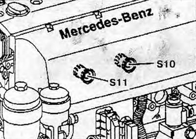
Figure 3.11b. Press the brake light switch 811, then the starter switch 810 and set the crankshaft to the position corresponding to the adjustment method.
5. Adjust the position of the double-sided rocker arms (only on engines with adjustable double-sided rocker arms).
6. Check and adjust the valve clearances (arrow) (figure 3.11c,d).
7. Remove the rotating device 4 and install the cover 3 (figure 3.11a).
8. Install the cylinder head cover.
- Thermal clearance of intake valves: 0.40 mm.
- Thermal clearance of exhaust valves: 0.60 mm.
- Permissible deviation from the specified value: -0.10/+0.20 mm
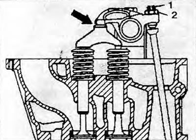
Figure 3.11c. Check and adjust the thermal clearance of the intake valves (arrow): 1 - Adjusting bolt; 2 - Lock nut.
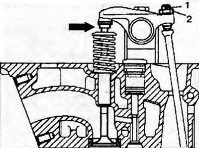
Figure 3.11d. Check and adjust the thermal clearance of the exhaust valve (arrow): 1 - Adjusting bolt; 2 - Lock nut.
11.1. Method 1 for adjusting the thermal clearance of the valves
Adjust the valves of each cylinder in the firing order: 1-3-4-2 (figure 3.11 d). The cylinder piston must be at TDC on the ignition stroke and the valve overlap at TDC must be synchronized. Valve overlap: 4-2-1-3.
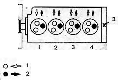
Figure 3.11d. Method 1 for adjusting the valve clearance: 1 - Exhaust valve; 2 - Inlet valve; 3 - Flywheel side.
11.2. Method 2 for adjusting the thermal clearance of valves
The valves are adjusted in two positions of the crankshaft (table 3.1). First, set the valve overlap of the 4th cylinder (in cylinder 1 at TDC on the ignition stroke), then set the valve overlap of the 1st cylinder (in cylinder 4 at TDC on the ignition stroke) (figure 3.11e).
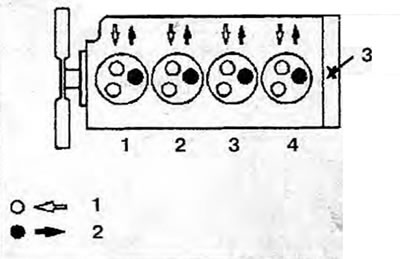
Figure 3.11e. Method 2 for adjusting the valve clearance: 1 - Exhaust valve; 2 - Inlet valve; 3 - Flywheel side.
Table 3.1. Method 2 for adjusting the thermal clearance of valves
| Crankshaft position | Adjusting cylinder valves | |||
| 1 | 2 | 3 | 4 | |
| Valve overlap of cylinder 4 | Inlet/outlet | Inlet | Outlet | - |
| Valve overlap of cylinder 1 | - | Outlet | Inlet | Inlet/outlet |