



Removal
1. Disconnect the negative cable from the battery.
2. Drain the coolant.
3. Remove the front passenger seat.
4. Remove the exhaust manifold.
5. Remove the fuel lines.
6. Disconnect the permanent throttle from the cylinder head.
7. Remove the fuel drain line 6 from the cylinder head 1 (figure 3.6). Replace seals 7.
8. Remove the oil level indicator pipe bracket 10 from the cylinder head 1.
9. Disconnect wiring connectors 16.1 or 16.2 from temperature sensor B8.1 or B8.2
10. Remove adapter 14.1 or 14.2 of the coolant pump from cylinder head 1. Replace connector 11 and gasket 15.
11. Remove the rocker arms and rocker arm shafts.
12. Remove the double-sided rocker arms 3.1 or 3.2.
13. Remove the push rods 4.
14. Unscrew the cylinder head mounting bolts 2.
15. Remove cylinder head 1 from the cylinder block.
16. Wipe threaded holes, oil passages and coolant passages.
17. Wipe the contact surfaces of the cylinder block.
Examination
18. Measure the length of the 2 cylinder head mounting bolts.
19. Wipe the cylinder head and check for damage.
20. Check the contact surfaces of cylinder head 1 and cylinder block for straightness:
- Permissible deviation from straightness of the lower contact surface of the cylinder head along the entire length: 0.05 mm.
- Permissible deviation from straightness of the lower contact surface of the cylinder head over a length of more than 150 mm: 0.02 mm.
- Permissible deviation from straightness of the contact surface of the cylinder block along the entire length: 0.03 mm.
- Permissible deviation from straightness of the contact surface of the cylinder block over a length of more than 150 mm: 0.015 mm.
Installation
21. Installation is carried out in the reverse order of removal.
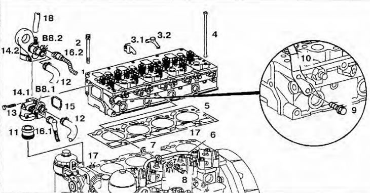
Figure 3.6. Cylinder head: 1 - Cylinder head; 2 - Cylinder head mounting bolt; 3.1 - Double-sided rocker arm (engine 904.904/908 up to number 039739); 3.2 - Double-sided rocker arm (engine 904.904/908, starting with number 039740, and 904.914/923/936); 4 - Push rod; 5 - Cylinder head gasket; 6 - Fuel drain line; 7 - Sealing ring; 8, 9, 13 - Bolts; 10 - Oil level indicator pipe bracket; 11 - Connector; 12, 1 8 - Cooling system pipes; 14.1 - Coolant pump adapter (engine 904.904/908 up to number 039739); 14.2 - Coolant pump adapter (engine 904.904/908, starting with number 039740, and 904.914/923/936); 15 - Gasket; 16.1 - Coolant Temperature Sensor Wiring Connector (engine 904.904/908 up to number 039739); 16.2 - Coolant Temperature Sensor Wiring Connector (engine 904.904/908, starting with number 039740, and 904.914/923/936); 17 - Centering bushings; B8.1 - Coolant temperature sensor (engine 904.904/908 up to number 039739); B8.2 - Coolant temperature sensor (engine 904.904/908, starting with number 039740, and 904.914/923/936).
(Material based on data from the portal: MERCEDESMAN)