



Removal
1. Remove the radiator.
2. Remove thermostat 4 (figure 3.28a).
3. Remove the fan clutch.
4. Remove the generator drive belt.
5. Remove pulley 15 of cooling system pump 1.
6. Remove bracket 12.
7. Disconnect wiring connector 7.1 or 7.2 from the coolant temperature sensor.
8. Remove adapters 8.1 or 8.2 from the cylinder head. Replace gasket 9.
9. Remove connector 6.
10. Disconnect the cooling system pipe 11 from the cooling system pump 1.
11. Remove the cooling system pump 1 and gasket 5.
12. Wipe the sealing surface of the cylinder block and coolant pump 1.
Disassembly
13. Remove flange 1 from shaft 3 (figure 3.28b).
14. Remove retaining ring 2.
15. Using a punch, remove shaft 3 from impeller 6 and pump body 4.
Assembly
16. Lubricate shaft 3 with engine oil and press it into pump body 4 using a punch.
17. Install retaining ring 2.
18. Heat flange 1 and press it onto shaft 3.
19. Install new seal 5 on shaft 3 and use a punch to press it into pump body 4.
20. Press impeller 6 onto shaft 3.
21. Rotate flange 1 of the pump and check the ease of rotation of the shaft.
- The gap between the impeller and the cooling system pump housing: 0.6-1.0 mm.
- Distance between the cooling system pump body and the flange: 112.7-113.3 mm.
- The protrusion of the impeller relative to the housing of the cooling system pump: 0.5 mm.
Installation
22. Installation is carried out in the reverse order of removal.
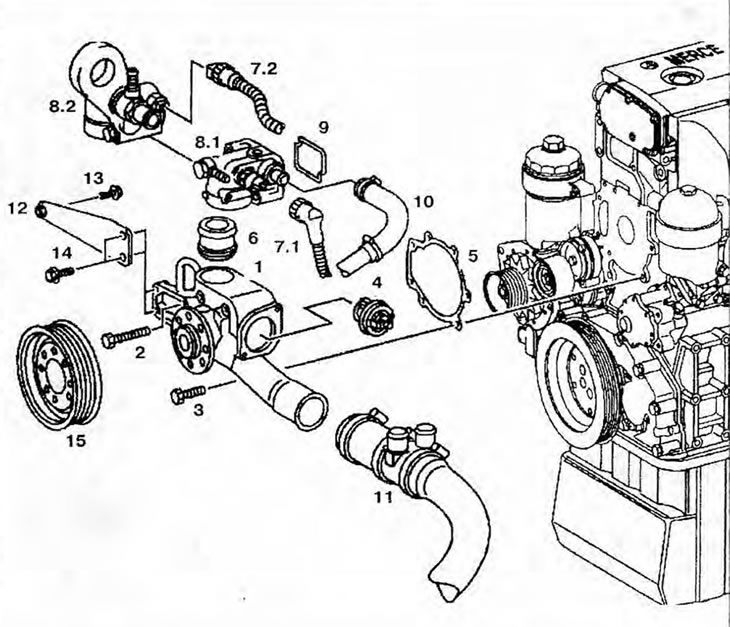
Figure 3.28a. Removing and installing the cooling system pump: 1 - Cooling system pump; 2, 3, 13, 14 - Bolts; 4 - Thermostat; 5, 9 - Gaskets; 6 - Connector; 7.1 - Coolant Temperature Sensor Wiring Connector (engines 904.904/908 up to number 040487); 7.2 - Coolant Temperature Sensor Wiring Connector (engines 904.904/908, starting with number 040488, and engines 904.914/923/936); 8.1 - Adapter (engines 904.904/908 up to number 040487); 8.2 - Adapter (engines 904.904/908, starting with number 040488, and engines 904.914/923/936); 10, 11 - Cooling system pipes; 12 - Bracket; 15 - Cooling system pump pulley.
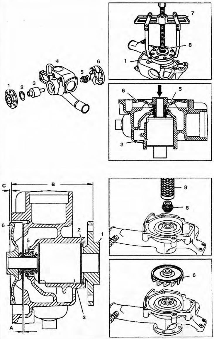
Figure 3.28b. Disassembling and assembling the cooling system pump: 1 - Flange; 2 - Retaining ring; 3 - Shaft; 4 - Cooling system pump housing; 5 - Seal; 6 - Blade wheel; 7 - Puller; 8 - Thrust piece; 9 - Punch; A - Clearance between the impeller and the housing of the cooling system pump; B - Distance between the cooling system pump housing and the flange, C - Protrusion of the impeller relative to the cooling system pump housing.