
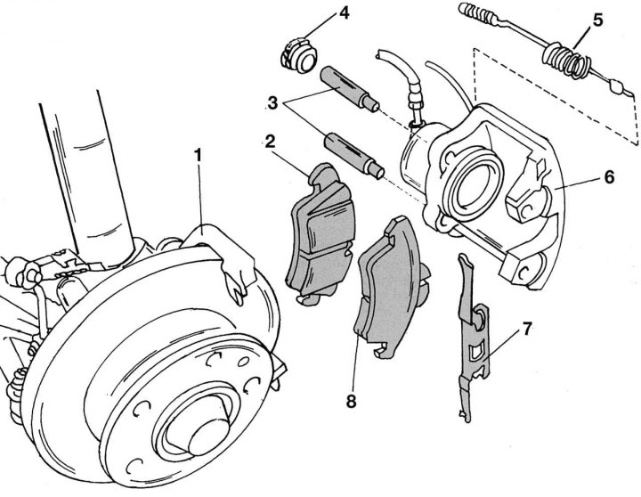
Pic. 269. The device of the front brake mechanism: 1 - brake caliper bracket (bolted to the front axle); 2 - inner shoe with retaining spring; 3 - guide pin, 25 Nm; 4 - plug; 5 - pad wear sensor with wire; 6 - caliper cylinder; 7 - spring; 8 - outer block
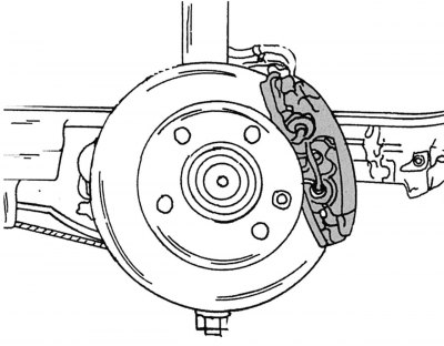
Pic. 270. The position of the brake caliper with the wheel removed
On fig. 269 shows the details of the brake caliper. The appearance and position of the caliper after removing the wheel, see fig. 270. Despite the fact that the removal process is considered here on the one hand, it is necessary to change the pads as a set:
- if old pads are installed, when removing them, they should be marked in accordance with the installation side and position (external, internal);
- with the engine off, press the brake pedal several times to remove the vacuum in the system;
- unscrew the cap of the brake fluid reservoir;
- loosen the wheel bolts, place the car in front on supports and remove the wheels;
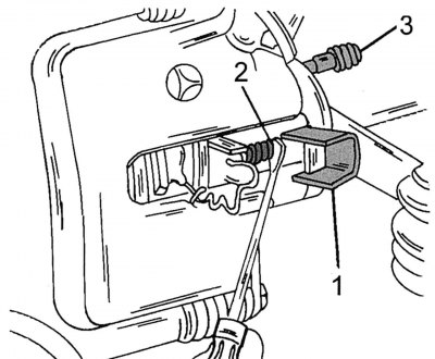
Pic. 271. Removing the spring (7 in fig. 269) with a screwdriver: 1 - cover; 2 - wire plug; 3 - bleed valve
- Disconnect the brake pad wear sensor wire. To do this, remove the cover and remove the plug (pic. 271);
- use a screwdriver to remove the connecting spring 7 (see fig. 269) between caliper and caliper bracket;
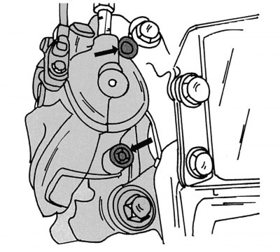
Pic. 272. Brake caliper mounting bolts (shown by arrows)
- on the reverse side of the caliper, remove the plugs from the fixing bolts with a screwdriver and unscrew them with a hexagon. Requires a straight hex wrench that can be inserted into a socket head. A bent hexagon is not suitable, since during installation it is necessary to tighten the bolts with a certain moment. After loosening the bolts shown in fig. 272, remove the caliper cylinder. Hang the cylinder on a wire to the front axle so that it does not hang on the brake hose;
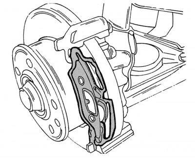
Pic. 273. Outer shoe
- remove the brake pad from the side of the caliper, the outer pad remains on the caliper bracket and is removed from the side of the brake disc (pic. 273). If the pad linings are worn to a thickness of 3.5 mm or less or they are oily, the pads should be replaced as a set. Even though pad linings can wear down to a thickness of 2 mm, the warning light in the instrument cluster comes on at 3.5 mm. Always replace both pads, even if one of them is not worn. If the pads are worn very badly, the piston may be stuck. In this case, the caliper should be returned for repair. For security reasons, this work is not described here;
- repair is also necessary if the dirt cover in the cylinder body is damaged. The pad wear sensor must be replaced if the insulation of the contact plate or any other part of it, including the wire, is damaged;
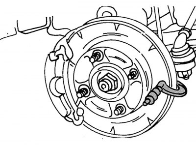
Pic. 274. Determination of brake disc wear
- check the surface of the brake discs and clean thoroughly before installing new pads. Measure the disc thickness as shown in fig. 274. It may need to be replaced or polished.
When installing the pads, you must perform the following operations:
- clean the contact surface under the brake pads in the caliper;
- pump out some brake fluid from the master cylinder reservoir as described above;
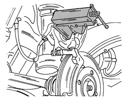
Pic. 275. Recessing the piston of the brake caliper before installing the pads
- push the piston into the cylinder. For this, a clamp is used, shown in Fig. 275;
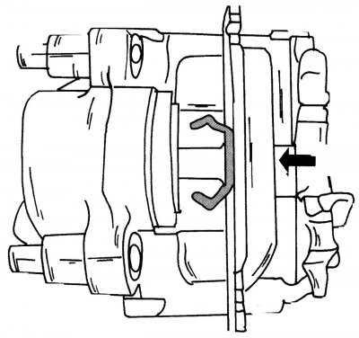
Pic. 276. Inner shoe
- install the shoe with the spring in the caliper cylinder, as shown in fig. 276, and press in the direction of the arrow;
- insert the outer pad into the mounting points of the caliper bracket so that it occupies the position shown in fig. 273;
- insert the second pad into the caliper bracket;
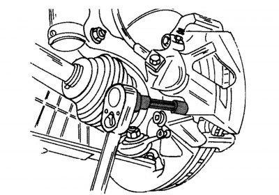
Pic. 277. Tightening the caliper mounting bolts
- carefully place the cylinder body over the pads and screw the mounting bolts through the pads into the caliper bracket. Wrap them with a hexagon, as shown in fig. 277, torque 25-28 Nm. The shape of the hexagon must correspond to that shown in the figure so that a torque wrench can be installed on it;
- after tightening the bolts, put plugs on them;
- insert the spring into the caliper and bracket;
- twist the wear sensor wire into a spiral and connect to the contact of the caliper. Install the cover of the plug connection;
- press the brake pedal hard several times so that the pads approach the disc;
- if necessary, add brake fluid to the reservoir;
- install the wheels, lower the car and tighten the wheel bolts to a torque of 160–180 N·m;
- after installation, depress the brake pedal several times until it reaches normal travel. If this is not done, the brakes may not work during the first check while driving. If the pedal «fails», check the tightness of the system. During the first kilometers after installing new pads, do not brake too hard. In order for the brakes to work well, you should brake several times with a smooth pressure on the pedal from a speed of 80 km / h to 40 km / h. After each braking, you need to wait a little so that the brakes do not overheat.