



Attention! Always replace all pads on one axle of the vehicle, even if only one pad has reached the wear limit. If the pads are to be reinstalled, they must be marked before removal.
Warning! When brake pads are in operation, brake dust is formed, which contains asbestos, which is harmful to health. Therefore, when cleaning brake pads, do not use compressed air and do not inhale the dust.
Removal the front brake pads
1. Apply the handbrake, then raise the front of the car and secure it on stands. Remove the front wheels.
Single piston sliding caliper models
Caution! New caliper guide pins must be used during installation.
Disconnecting the brake pad wear sensor electrical connector on single piston sliding caliper models
Unscrewing the caliper guide pin mounting bolt
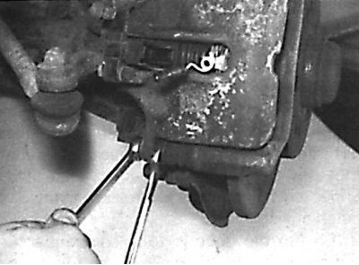
In this case, it is necessary to use a thin wrench to keep the guide pin from turning.
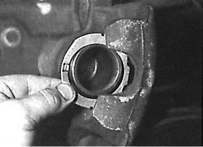
Removal the gasket from the caliper piston
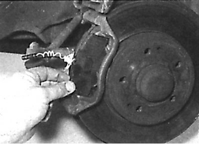
Installing a brake pad with a wear sensor
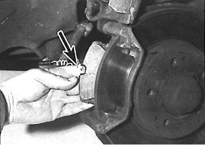
Install the brake pad with the wear sensor on the inside.
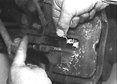
Pulling the brake pad wear sensor wiring through the window in the caliper
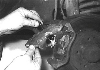
Installing a new guide pin mounting bolt

1. Remove the retaining clips and disconnect the brake pad wear sensor electrical connector cover from the caliper.
2. Disconnect the brake pad wear sensor electrical connector from the caliper bracket (see Fig. Disconnecting the electrical connector of the brake pad wear sensor on models with a single-piston sliding caliper).
3. Unscrew the lower bolt securing the caliper guide pin. Use a thin wrench to hold the guide pin from turning (see fig. Unscrewing the caliper guide pin mounting bolt). A new bolt must be used during installation.
4. After unscrewing the lower guide pin mounting bolt, rotate the caliper upward until the brake pads are released. Remove the gasket from the caliper piston (see fig. Removing the gasket from the caliper piston).
5. Mark the position of the brake pads and remove them from the caliper holder.
6. Measure the brake pad friction lining thickness and, if it is worn down to the minimum thickness at any point, replace all four front brake pads. The pads must also be replaced if any of the pads are contaminated with oil, as there is no way to degrease brake pads. If the brake pads are unevenly worn or contaminated with oil, identify and eliminate the cause before installing new brake pads. Check the condition of the brake pad wear sensor and replace it if necessary.
7. If the brake pads are to be reinstalled, clean them on all sides. Clean any dirt from the brake pad grooves, and be careful to clean the brake pad mounting area in the caliper carrier.
8. Before installing the brake pads, check the condition of the guide pins and their freedom of movement in the caliper holder. Check the condition of the guide pin protective boots. Clean the caliper and pistons from dirt and dust. Check the condition of the dust cover located around the piston. Using a suitable tap, clean the guide pin threads.
9. If new brake pads are to be installed, press the piston into the caliper with a wooden rod or hammer handle. Make sure that the piston is not warped and that the surfaces of the piston and dust cover are not damaged. When the piston is pushed in, the brake fluid is forced out of the brake cylinder into the refill tank, so constantly monitor the fluid level in the tank and, if necessary, pump out a small amount of it from the tank.
10. Lubricate the backing plate of each brake shoe with brake paste No.0019891051. Apply only a thin layer of grease and avoid getting grease on the friction lining of the brake shoe.
11. Install the brake pad wear sensor, then install the brake pads into the caliper holder so that the friction linings of the brake pads are aligned with the working surface of the brake disc. Note that the brake pad wear sensor is installed on the inner brake pad (see fig. Installing a brake pad with a wear sensor).
12. Install the spacer onto the caliper piston, then rotate the caliper and position it over the brake pads, passing the brake pad wear sensor wiring through the window in the caliper (see fig. Pulling the brake pad wear sensor wiring through the window in the caliper).
13. Check that the springs that compress the brake pads are correctly positioned in the caliper, then press on the caliper, press and tighten the guide pin mounting bolt (see Fig. Installing a new guide pin mounting bolt). When tightening the guide pin mounting bolt to the required torque, hold the guide pin from turning with a thin wrench.
14. Install the brake pad wear sensor electrical connector onto the caliper. Wrap the sensor wire around the connector to prevent it from dangling. Check that the connector is installed correctly and install the sensor cover into the caliper window.
15. Press the brake pedal several times to press the brake pads against the brake disc. Check the brake fluid level in the reservoir.
16. Repeat the above steps on the second wheel.
17. Install the wheels and lower the vehicle.
18. Check the brake fluid level.
Fixed caliper, twin piston models
Disconnecting the brake pad wear electrical connector on twin piston fixed caliper models
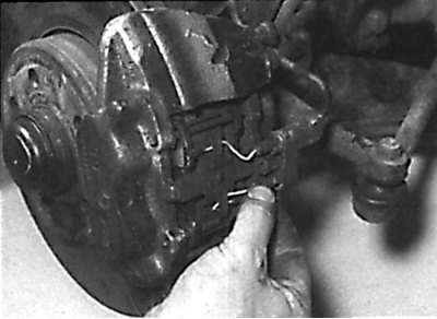
Knocking out brake shoe mounting pins
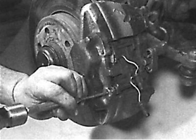
Removal the spring from the caliper that presses the brake pads
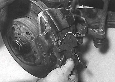
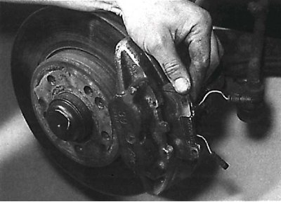
Removal brake pads with linings from the caliper
Shock absorber stops on the brake shoe
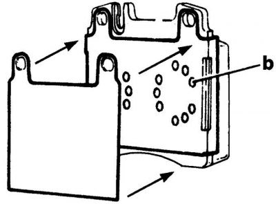
If the brake shoe has shock absorber stops (b), it is not necessary to apply a layer of grease to the end surface of the support plate.
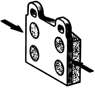
If the brake shoe does not have shock absorber stops, apply a thin layer of grease to the end surface of the support plate (arrows).
1. Remove and disconnect the brake pad wear sensor electrical connector from the caliper. Note the location of the sensor wiring (see Fig. Disconnecting the Brake Pad Wear Electrical Connector on Twin Piston Fixed Caliper Models).
2. Using a hammer and appropriate punch, carefully tap out the brake shoe mounting pins and remove the spring that compresses the brake shoes (see fig. Knocking out the brake pad mounting pins, Removing the spring from the caliper that presses the brake pads).
3. Remove the brake pads from the caliper, noting the location of the brake pad wear sensors. If present, remove the linings installed between the brake pads and pistons (see Fig. Removing brake pads with linings from the caliper).
4. Measure the brake pad friction lining thickness and, if it is worn down to the minimum thickness at any point, replace all four front brake pads. The pads must also be replaced if any of the pads are contaminated with oil, as there is no way to degrease brake pads. If the brake pads are unevenly worn or contaminated with oil, identify and eliminate the cause before installing new brake pads. Check the condition of the brake pad wear sensor and replace it if necessary.
5. If the brake pads are to be reinstalled, clean them on all sides. Clean any dirt from the brake pad grooves, and be careful to clean the brake pad mounting area in the caliper carrier. When installing new brake pads, also replace the brake pad spring, pins, and shims.
6. Clean the caliper and pistons from dirt and dust. When cleaning, do not inhale the dust, as it contains asbestos, which is harmful to health. Check the condition of the dust covers installed around each piston.
7. If new brake pads are to be installed, press the pistons into the caliper with a wooden rod or hammer handle. Make sure that the pistons are not warped and that the surfaces of the pistons and protective boots are not damaged. When the pistons are pushed in, the brake fluid is forced out of the brake cylinders into the replenishing reservoir, so constantly monitor the fluid level in the reservoir and, if necessary, pump out a small amount of it from the reservoir.
Caution! Use a syringe to pump out brake fluid from the reservoir.
8. If the rear part of the brake pads is equipped with shock-absorbing stops for the caliper pistons, do not apply a layer of grease to the support plates of the brake pads. If there are no shock-absorbing stops on the brake pads, lubricate the end surface of the support plate of the brake pad with brake grease 0019891051. Apply the grease in a thin layer and avoid getting grease on the linings of the brake pads (see fig. Shock absorber stops on the brake shoe).
9. Check that the brake pad wear sensors are correctly installed on the brake pad backing plates and install shims on the back of the brake pads.
10. Install the brake pads with linings into the caliper so that the lining of each brake pad is positioned opposite the working surface of the brake disc.
11. Install a new brake shoe spring.
12. Insert the brake pad retaining pins so that they pass over the spring that compresses the brake pads, and then press them completely into the caliper.
13. Check the wiring placement and then insert the brake pad wear sensor electrical connectors into the caliper.
14. Press the brake pedal several times to press the brake pads against the caliper. Check the brake fluid level in the reservoir.
15. Repeat the above steps on the second wheel.
16. Install the wheels and lower the vehicle.
17. Check the brake fluid level.