
Removing
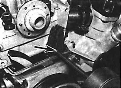
Using an inertia hammer to remove the top locating pin of the drive chain guide
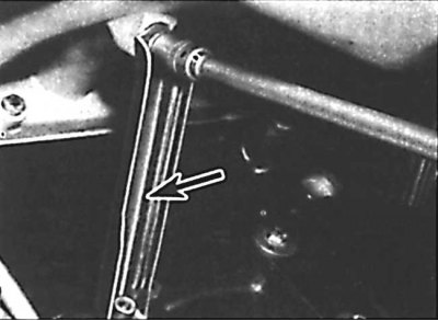
Unscrewing the intake manifold support bracket bolt
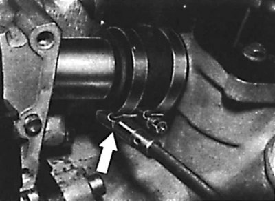
An arrangement of a collar of fastening of a hose of the water pump to a head of the block of cylinders
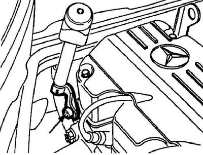
The location of the pipe bolt for the dipstick for measuring the oil level in an automatic transmission to the cylinder head
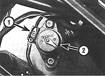
Terminal block location (1) on the diagnostic connector bracket (2)
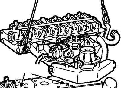
Removing the cylinder head from the engine
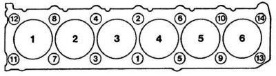
Cylinder head bolt tightening sequence
1. The cylinder head is removed on a cold engine along with the intake and exhaust manifolds.
2. Remove the ground wire from the battery.
3. Open and place the hood in a vertical position.
4. Drain the coolant from the cooling system.
5. Remove the camshaft sprocket.
6. Screw an additional bolt into the upper dowel pin of the chain guide. Using an inertia hammer and an adapter, remove the chain guide locating pin by the head of the bolt (see fig. Using an inertia hammer to remove the top locating pin of the drive chain guide).
7. Remove the bolt securing the dipstick pipe bracket to the cylinder head.
8. Unscrew and remove the two intake manifold support brackets (see fig. Unscrewing the intake manifold support bracket bolt).
9. Loosen the clamp and remove the short water pump hose from the cylinder head (see fig. An arrangement of a collar of fastening of a hose of the water pump to a head of the block of cylinders).
10. Loosen the clamp and remove the heater coolant return hose from the fitting on the back of the cylinder head.
11. On models with automatic transmission, unscrew the bolt securing the dipstick tube to the cylinder head (see fig. The location of the pipe bolt for the dipstick for measuring the oil level in an automatic transmission to the cylinder head).
12. Depressurize the fuel system and disconnect the supply and return fuel lines.
13. Disconnect the accelerator cable from the throttle lever.
14. On automatic transmission models, disconnect the pressure control cable from the throttle linkage.
15. Label and disconnect all electrical connectors from the cylinder head.
16. Remove the engine wiring harness from the engine mounting brackets.
17. Disconnect the vacuum hose and electrical connector from the ignition control unit.
18. Unscrew the screw and disconnect the wire from the terminal block on the diagnostic connector bracket (see fig. Location of the terminal block on the bracket of the diagnostic connector).
19. Unscrew the diagnostic connector and disconnect the gray connector on the left side of the socket.
20. Disconnect the exhaust pipe from the exhaust manifold.
21. Check that all hoses and electrical connectors are disconnected from the cylinder head.
22. Evenly and gradually loosen the cylinder head bolts in the reverse order shown in the figure. Sequence of tightening the cylinder head bolts.
23. Remove the cylinder head bolts.
24. Hook the cylinder head with the slings of the lifting mechanism and, being careful, lift the head and remove it from the engine compartment (see fig. Removing the cylinder head from the engine).
25. Remove the cylinder head gasket.
Preparing the head for installation
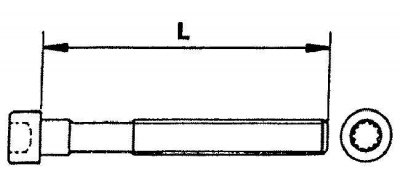
Measuring the length of the cylinder head bolt
1. The mating surfaces of the head and cylinder block must be perfectly clean. Use a hard plastic or wooden scraper to clean them. Be careful when cleaning as aluminum alloy is very easy to damage. Check that carbon deposits do not get into the oil and water channels. This is especially important for the lubrication system, as deposits can block the oil supply to engine components. If necessary, clean the channels, check the mating surfaces of the head and cylinder block for nicks, deep scratches and other damage. If the defects are small, they can be removed by machining. In case of significant defects, the parts must be replaced.
2. Using a metal ruler and feeler gauge, check the flatness of the mating surfaces.
3. Clean the bolt holes in the cylinder block. Screwing a bolt into oil-filled holes can rupture the block due to hydraulic pressure.
4. Measure the length of the bolts from the base of the head (see fig. Measuring the length of the cylinder head bolt). If the bolt length exceeds the allowable limits, replace all the bolts in the kit.
Installation
1. Check that the timing marks on the crankshaft and camshaft are aligned with the pointers.
2. Install the cylinder head gasket onto the guide pins on the cylinder block.
3. Being careful, establish a head of the block of cylinders.
4. Lubricate the threads and bottom surface of the bolt head, insert the cylinder head bolts and screw them in by hand.
5. Gradually and evenly in several stages, tighten the cylinder head bolts in the sequence shown in Figure Cylinder head bolt tightening sequence.
6. Connect the exhaust pipe to the exhaust manifold.
7. Connect the vacuum hoses and electrical connectors to the cylinder head. Secure the engine wiring harness with clips.
8. On automatic transmission models, connect the pressure control cable to the throttle linkage.
9. Connect the accelerator cable to the throttle lever.
10. Connect the supply and return fuel lines.
11. On automatic transmission models, attach the transmission oil dipstick tube to the engine.
12. Install the coolant supply hose to the heater on the fitting on the back of the cylinder head. Connect the coolant supply hose from the water pump.
13. Install the two intake manifold support brackets.
14. Screw in the bolt securing the pipe bracket for the dipstick to measure the engine oil level to the cylinder head.
15. Check that the drive chain damper is correctly positioned and install the damper locating pin.
16. Install the camshaft sprocket.
17. Add coolant to the cooling system.
18. Connect the ground wire to the battery and close the hood.