



Attention! Valve drive and oil sprayer parts have many modifications, so when replacing them, you must consult a Mercedes-Benz representative.
Location of the front camshaft bearing cover mounting bolts
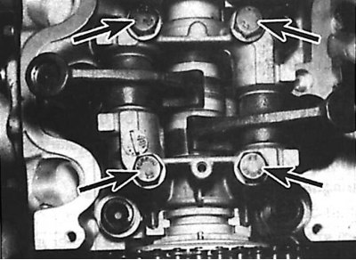
The valve drive is combined with the camshaft bearing caps. The rocker arms are mounted on separate short axles, which are also secured to the camshaft bearing caps. Each camshaft bearing cap has one rocker arm, controlling the intake and exhaust valves.
Hydraulic tappets are fixed in the rocker arms, and oil is supplied to them through holes in the rocker arms.
Publication reprinted from this resource MERCEDESMAN.ru
Removal
1. Remove the air filter.
2. Remove the camshaft sprocket.
3. Remove the bolts and oil spray from the top of the camshaft bearing caps.
4. Check that the rocker arms and bearing caps are marked. The bearing caps are numbered 1 through 6 on the camshaft sprocket side, and the bearing caps are numbered on the exhaust manifold side. Similar markings are also found on the cylinder head under the camshaft.
5. Loosen the camshaft bearing cap bolts evenly and gradually in a diagonal sequence. Once the valve spring pressure has been released, loosen the bolts completely. When loosening the bolts, mark the location of the engine oil spray tube brackets.
6. Remove the camshaft bearing caps with the rocker arms attached to them. The camshaft bearing caps are installed on the guide pins.
7. Remove the camshaft. If present, remove the camshaft end play adjusting washer located near the front bearing.
Disassembly, inspection and assembly
Camshaft
1. Check the camshaft bearing running surfaces and camshaft lobe contours for wear. If any wear is present, replace the camshaft. When replacing the camshaft, the rocker arms must also be replaced.
Valve drive
Using M8 bolt (1) to remove the valve rocker shaft
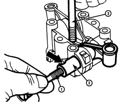
When installing the axle, the recess on the side of the axle (arrow) must align with the bolt (3) securing the camshaft bearing cover
1. Once the camshaft bearing caps have been removed from the bearing caps, the rocker arms can be removed by pulling the short rocker shafts out of the caps. Before removing the rocker arms, check that they are marked and note the location of the rocker arms relative to the camshaft bearing cap.
2. To remove the rocker shaft from the camshaft bearing cap, use an inertia hammer with a special adapter. Alternatively, screw a long M8 bolt with a washer into the rocker shaft and, hitting the washer with a hammer, pull the rocker shaft out of the camshaft bearing cap (see Fig. Using M8 bolt to remove rocker shaft). After removing the axle, remove the rocker arm. Store the removed parts so that they can be installed in their places later.
3. Check the condition of the contact washers for wear. If there is wear, the part in the set must be replaced.
4. Lubricate the rocker arm working surfaces with clean engine oil, then install the rocker arms on the cover and secure them with the axle. When reinstalling the parts, check that they are in place. Install the rocker arm axles so that the recess for the camshaft bearing cover mounting bolt in each axle aligns with the hole for the bolt in the bearing cover. If there are no special tools for pressing in the rocker arm axle, press in the axle using a long M8 bolt and a hammer.
Hydraulic tappets
Rocker arm parts
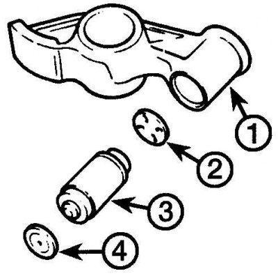
1 – rocker arm; 2 – spacer washer; 3 – hydraulic pusher; 4 – contact washer
Checking the serviceability of the hydraulic valve lifter
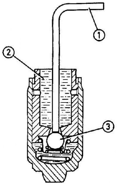
1 – steel wire with a diameter of 1.5 mm; 2 – oil supply chamber; 3 – ball valve
1. To remove the tappet from the rocker arm, insert a suitable drift through the hole in the top of the rocker arm and press the tappet out of the rocker arm.
2. Remove the spacer washer from the pushrod socket in the rocker arm (see fig. Rocker arm parts).
3. Arrange the rocker arm parts in such a way that they can be installed in their proper places later.
4. Check the condition of the tappets and replace them if necessary.
5. The serviceability of hydraulic tappets can be checked as follows: (see fig. Checking the serviceability of the hydraulic valve tappet):
- a - install the hydraulic valve lifter vertically;
- b - fill the oil feed chamber at the top of the tappet with clean engine oil;
- c - using a 1.5 mm diameter steel wire inserted through the hole in the center of the tappet, press the ball valve and release it. Press the ball valve until the working chamber of the hydraulic tappet is filled with oil;
- d - using a wooden hammer handle, press hard on the top of the plunger piston for 10 seconds. The plunger piston should remain in place;
- e - if the pusher piston moves downwards, the pusher must be replaced.
6. Hydraulic valve tappets are designed in such a way that the tappet stroke to compensate for valve clearance is insignificant. This is due to the small dimensions of the hydraulic valve tappets. In order for the hydraulic tappet stroke to be sufficient to compensate for valve clearances, spacer washers of different thicknesses are used.
7. If you hear valve knocking when the engine is running, the valve clearance may not meet the technical requirements. In this case, you need to install a new spacer washer of a different thickness.
8. To determine the required thickness of the spacer washer, a special tool must be used and this work must be performed at a service station.
9. Before installing hydraulic tappets, they must be filled with engine oil. To do this, install the tappets vertically in a container filled with clean engine oil. Press the ball valve with a thin steel wire and, moving the tappet plunger upward, introduce oil into the working cavity of the tappet. Repeat this operation until the working chamber of the hydraulic tappet is completely filled with oil.
10. Install the spacer washer into the tappet seat in the rocker arm with the oil passage of the washer facing the hydraulic tappet. Install the hydraulic tappet into the rocker arm.
Installation
1. Check that the camshaft end play adjusting washer is installed near the front bearing.
2. Lubricate the camshaft journals and cams and the bearings in the caps and cylinder head with clean engine oil and install the camshaft in the cylinder head. Turn the camshaft so that the recess in the flange at the front of the camshaft aligns with the top plane of the cylinder head.
3. Install contact washers on top of the valves.
4. Install the camshaft bearing caps with the cap markings facing the exhaust manifold side.
5. Install the oil sprayer, making sure that the oil supply holes in the sprayer are aligned with the corresponding holes in the camshaft bearing caps.
6. Insert the camshaft bearing cap bolts and tighten them finger tight, then tighten the cap bolts in a diagonal pattern, gradually turning each bolt one-half turn at a time until each cap contacts the cylinder head. Then tighten the bolts to the specified torque in the same pattern.
7. Check that the timing marks are aligned with the pointers, then install the camshaft sprocket.
8. Install the cylinder head cover.
9. Install the air filter.