
Principle of hydraulic valve clearance compensation
On engines M 102.980 and M 102.982, the rocker arms have hydraulic tappets.
Hydraulic valve lifter
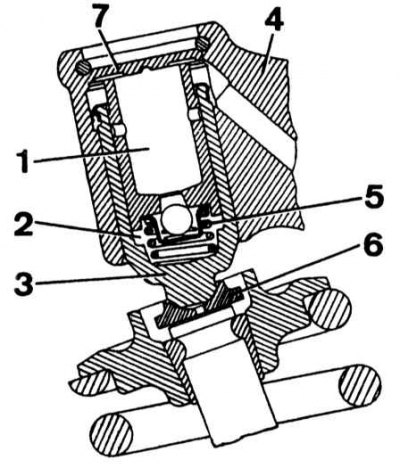
1 - storage chamber; 2 - working chamber; 3 - pusher; 4 - rocker; 5 - ball valve return spring; 6 - pusher plate; 7 - pusher thrust washer
During engine operation, low-pressure oil enters storage 1 and working 2 chambers (no more than 3 kg/cm2). This ensures constant contact of the pusher 3 with the valve stem. When the rocker arm 4 is lifted by the cam, the pusher enters the rocker arm, the ball valve closes, which causes an increase in pressure in the working chamber. Due to the incompressibility of the oil, the movement from the cam and rocker is transmitted to the pusher and valve. Spring 5 provides constant pusher pressure on the valves even when the engine is stopped.
Examination
If there is any doubt about the failure of the pushers (knocking, deterioration of the engine), check their condition.
1. Remove the cylinder head cover.
2. Turn the engine crankshaft by hand so that the back of the rocker arm faces the camshaft cam.
3. Measure the stroke of the pusher against the stop in the rocker arm. If the stroke exceeds 0.5-2.4 mm, change the thickness of the spherical plate 6 or thrust washer 7 of the pusher.
4. If one of the pushers drops faster than the others, then it should be removed and replaced.