
2. Raise the rear of the car and secure it on stands. Remove the corresponding rear wheel.
Upper camber arm
Mounting the upper arm that determines the camber
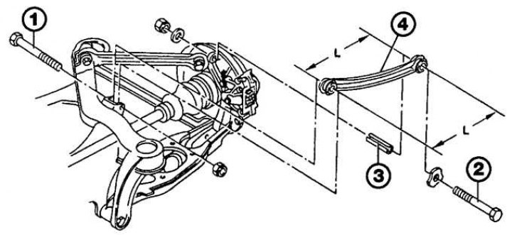
1 - internal hinge bolt; 2 - external hinge bolt; 3 - mounting sleeve; 4 - lever; L=314±0.5mm
1. Unscrew the nut and remove the pivot bolt securing the arm to the hub fastener (see fig. Mounting the upper arm that determines the camber).
2. Loosen the nut and remove the pivot bolt securing the rear camber arm to the lower frame and remove the arm from under the vehicle.
3. If necessary, press the mounting sleeve out of the lever on the side of the fastener.
4. Check the condition of the lever for mechanical damage. Pay special attention to the lever rubber bushings and check them for cracks and aging and replace them if necessary.
Upper reaction arm
Elements of fastening of the top jet lever
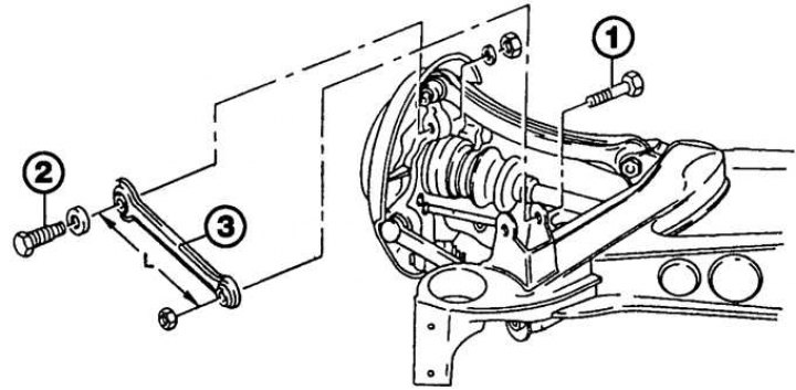
1 - internal hinge bolt; 2 - external hinge bolt; 3 - lever; L=247±0.5mm
1. Unscrew the nut and remove the pivot bolt securing the arm to the hub fastener (see fig. Elements of fastening of the top jet lever).
2. Loosen the nut and remove the pivot bolt securing the rear camber arm to the lower frame and remove the arm from under the vehicle.
3. Check the condition of the lever for mechanical damage. Pay special attention to the lever rubber bushings and check them for cracks and aging and replace them if necessary.
Lower Thrust Compensation Arm
Elements of fastening of the lower lever of compensation of axial pressure
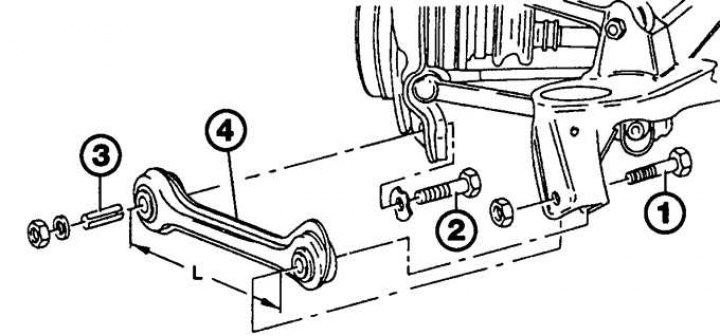
1 - internal hinge bolt; 2 - external hinge bolt; 3 - mounting sleeve; 4 - lever; L=314±0.5mm
1. Unscrew the nut and remove the pivot bolt securing the arm to the hub fastener (see fig. Elements of fastening of the lower lever of compensation of axial pressure).
2. Loosen the nut and remove the pivot bolt securing the rear camber arm to the lower frame and remove the arm from under the vehicle. If necessary, press the mounting sleeve out of the lever on the side of the fastener.
3. Check the condition of the lever for mechanical damage. Pay special attention to the lever rubber bushings and check them for cracks and aging and replace them if necessary.
Lower guide arm
Fastening elements of the lower guide arm
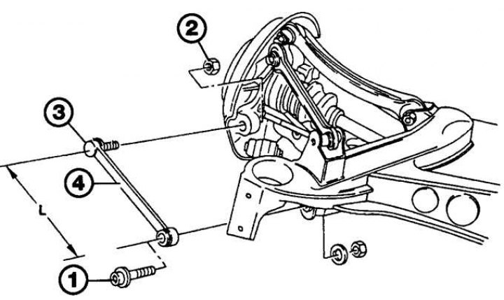
1 - internal hinge bolt; 2 - nut; 3 - external hinge bolt; 4 - lever; L=245±0.5mm
1. Place alignment marks on inner pivot bolt, eccentric washers and bottom frame before removing arm (see fig. Fastening elements of the lower guide arm). These marks must be used when installing the lever to maintain the convergence of the rear wheels.
2. Unscrew the nut, remove the eccentric washer and remove the pivot bolt securing the arm to the lower frame.
3. Unscrew the nut from the ball joint trunnion, then remove the ball joint from the hub fastener and remove the lever. A puller must be used when removing the ball joint trunnion and hub retainer.
4. Check the condition of the bushing for wear and damage, as well as check the free movement of the ball joint and the condition of its protective boot. Replace lever if necessary.
Installation
Upper camber arm
1. If necessary, press the mounting sleeve into the hub fastener.
2. Reinstall the lever, insert the hinge bolts and screw new nuts onto them, without completely tightening them.
3. Install the rear wheel, then lower the vehicle to the ground and tighten the wheel bolts to the correct torque.
4. Rock the vehicle until the arm mounting elements are in place, then tighten both pivot bolt nuts to the correct torque.
Upper reaction arm
1. Reinstall the lever, insert the hinge bolts and screw new nuts onto them, without completely tightening them.
2. Install the rear wheel, then lower the vehicle to the ground and tighten the wheel bolts to the correct torque.
3. Rock the vehicle until the arm mounting elements are in place, then tighten both pivot bolt nuts to the correct torque.
Lower Thrust Compensation Arm
1. If necessary, press the mounting sleeve into the hub fastener.
2. Reinstall the lever, insert the hinge bolts and screw new nuts onto them, without completely tightening them.
3. Install the rear wheel, then lower the vehicle to the ground and tighten the wheel bolts to the correct torque.
4. Rock the vehicle until the arm mounting elements are in place, then tighten both pivot bolt nuts to the correct torque.
Lower guide arm
1. Reinstall the lever, then insert the inner pivot bolt and eccentric washer and thread a new nut onto the bolt, but do not fully tighten it.
2. Install the ball joint trunnion on the hub fastener and secure with a new nut, tightening it to the required torque.
3. Install the rear wheel, then lower the vehicle to the ground and torque tighten the mounting bolts.
4. Rock the vehicle to properly install the arm, check that the marks on the lower frame, pivot bolt and eccentric washer are aligned, then tighten the pivot bolt nut to the correct torque.
Attention! Check rear wheel alignment as soon as possible.