
Pressure relief
1. Before disconnecting any of the hoses, the self-levelling rear suspension hydraulic system must be depressurized.
2. Raise the rear of the car and secure it on stands.
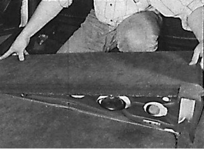
3. Working under the vehicle, clean the bleeder valve at the top of the Self Leveling Rear Suspension System control box.
4. Put a clean transparent hose on the bleeder fitting, place the other end in a container.
5. Loosen the bleed screw on the control box, drain 500 mm of fluid into a container and tighten the bleed plug to the required torque.
Filling the hydraulic system with the rear of the vehicle raised
Attention! At installation it is necessary to use a new nut of fastening of connecting draft of the control unit.
1. Raise the fluid level in the pressure accumulator of the self-levelling rear suspension control system to the maximum level.
2. Unscrew the nut securing the connecting rod to the control box lever. Remove the rod from the lever and move the lever up until it stops.
3. Start the engine, then increase the engine speed to 2,000 - 3,000 rpm and let it run at this speed for 30 seconds, then turn off the engine.
4. Connect the connecting rod to the lever of the control unit by installing it in the outer hole of the lever, then screw on a new fastening nut and tighten it to the required torque.
5. Check the fluid level in the pressure accumulator of the self-levelling rear suspension system.
Filling the system on a vehicle mounted on wheels
1. Raise the fluid level on the self-levelling rear suspension system pressure accumulator to the maximum level.
2. Place a load of 120 kg in the trunk. In this case, the control unit will be set to a position in which it is possible to fill and bleed the hydraulic system.
3. Start the engine, increase its speed to 2000-3000 rpm and let it run at this speed for 1 minute, then turn it off.
4. Remove the cargo from the trunk and check the fluid level in the self-levelling rear suspension system pressure accumulator.
Rear shock absorber
Attention! When installing the rear shock absorber, it is necessary to use a new shock absorber upper mounting bolt and a new shock absorber lower mounting nut, as well as a new pressure hose O-ring.
Removing
Removing the front part of the luggage compartment floor covering
The location of the upper shock absorber mounting bolt
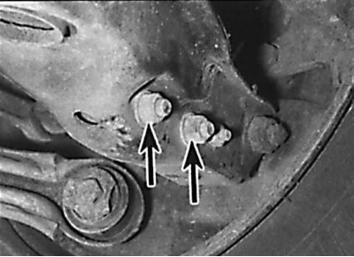
The location of the mounting bolts of the lower part of the shock absorber
1. Raise the rear of the car and secure it on stands. Remove the corresponding rear wheel.
2. Unscrew the screws and remove the protective cover from the base of the lower rear suspension arm. Support the lower rear suspension arm with a jack through a block of wood.
3. Depressurize the hydraulic system.
4. Wipe the area around the pressure accumulator connections and place a rag to catch any spillage. Unscrew the connecting bolt that secures the shock absorber pressure hose to the top of the pressure accumulator, remove the hose and O-rings. Plug the end of the hose and the hole in the pressure accumulator.
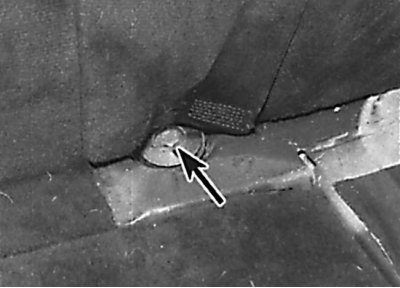
5. To improve access to the upper mounting bolt, remove the rear seat backs, then unscrew the screws and remove the front part of the luggage compartment floor cover. To access the rear mounting screws, lift the trim panel off the luggage compartment floor. Remove the side trim panel from the luggage compartment floor (see fig. Removing the front part of the floor covering of the luggage compartment, Location of the upper shock absorber mounting bolt).
6. Unscrew the upper shock absorber mounting bolt and remove the washer and rubber cushion.
7. Unscrew the nuts from the shock absorber lower mounting bolts and remove the bolts (see fig. The location of the mounting bolts of the lower part of the shock absorber). Remove the shock absorber from under the wheel arch and remove the rubber cushion from it.
8. Check the condition of the shock absorber for fluid leaks and mechanical damage and replace if necessary.
Installation
1. Install the rubber cushion on the shock absorber rod and install the shock absorber in place.
2. Align the lower part of the shock absorber with the rear suspension arm, install the mounting bolts, screw new nuts onto them, without completely tightening them.
3. Correctly position the shock absorber rod on the body and install the rubber pad and washer. Screw in a new bolt of fastening of the top part of the shock-absorber and tighten it by the demanded moment.
4. Install the luggage compartment floor panel and screw it on.
5. Connect the shock absorber pressure hose to the pressure accumulator by installing gaskets on both sides of the hose coupling, and secure the hose with the connecting bolt, tightening it to the required torque.
6. Torque tighten the nuts of the shock absorber lower mounting bolts. Install the protective cover on the base of the lower rear suspension arm.
7. Install the wheel, then lower the vehicle to the ground and tighten the wheel bolts to the correct torque.
8. Fill the hydraulic system with fluid.
Pressure accumulator
Removing
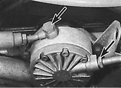
Connection points for tube and pressure hose (1) to the pressure accumulator and the location of the mounting bolts (2) pressure accumulator
1. Depressurize the hydraulic system.
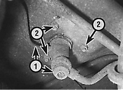
2. Wipe the area around the pressure accumulator connection and place a rag to catch the spilled liquid. Remove the connecting bolt securing the shock absorber pressure hose to the top of the pressure accumulator and remove the gasket. Unscrew the union nut and remove the tube from the pressure accumulator connecting the pressure accumulator to the control unit (see picture).
3. Remove the nuts securing the pressure accumulator to the underside of the vehicle.
4. To access the upper mounting bolt, remove the rear seat backs, then unscrew the screws and remove the front part of the luggage compartment floor cover. To access the rear mounting screws, remove the panel from the floor of the luggage compartment. The pressure accumulator can now be removed from the vehicle.
Installation
1. Install the pressure accumulator in place, then screw on the new fastening nuts and tighten them to the required torque.
2. Connect a hose and tube to the pressure accumulator. At the same time, install gaskets on both sides of the hose coupling and secure them with a nut and bolt, tightening them to the required torque.
3. Place the panel on the luggage compartment floor and secure with screws.
4. Fill the hydraulic system with fluid.
Control block
Attention! When installing the control box, you must use a new nut that secures the connecting rod to the control box lever.
Removing
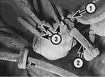
Location on the control unit of the bleed valve (1), tie rod (2) and piping connections (3)
1. Depressurize the hydraulic system.
2. Clean the area around the tubing connection to the control box. Mark the tubes so that they are not mixed up during installation (see picture).
3. Unscrew the union nuts and remove the hydraulic pipes from the control box. Close the holes in the control unit and the ends of the tubes with plugs.
4. Unscrew the nut and remove the connecting rod from the control box lever.
5. Unscrew the mounting bolts, remove the control unit and remove it from under the car.
Installation
1. Install the control box in place and secure with bolts, tightening them to the required torque.
2. Connect the tubes to the control unit and secure them with the union nuts, tightening them to the required torque.
3. Raise the fluid level in the pressure accumulator of the self-levelling rear suspension control system to the maximum level.
4. Unscrew the nut securing the connecting rod to the control box lever. Remove the rod from the lever and move the lever up until it stops.
5. Start the engine, then increase the engine speed to 2000-3000 rpm and let it run at this speed for 30 seconds, then turn off the engine.
6. Connect the connecting rod to the lever of the control unit by installing it in the outer hole of the lever, then screw on a new fastening nut and tighten it to the required torque.
7. Check the fluid level in the pressure accumulator of the self-levelling rear suspension system.
Connecting rod control unit
Attention! At installation it is necessary to use new nuts and a bolt of fastening of connecting draft.
Removing
1. Raise the rear of the car and secure it on stands.
2. Unscrew the fastening nut and bolt and remove the connecting rod from under the car. Check the condition of the connecting rod for wear or mechanical damage and, if necessary, replace it. Check that the tie rod bracket is securely fastened to the anti-roll bar.
Installation
1. Install the connecting rod in place so that the ball joint of the rod is installed in the outer hole of the control box lever. Install a new bolt and nut securing the tie rod to the anti-roll bar bracket. Tighten the nuts to the required torque and lower the car.
Hydraulic pump on 4-cylinder petrol and non-turbo diesel models
Removing
Places of connection to the hydraulic pump tube and hose
1. Depressurize the hydraulic system.
2. Wipe the area near the hydraulic pump connections, then unscrew the connecting bolt and nut and disconnect the tube and hose from the hydraulic pump (see fig. Places of connection to the hydraulic pump tube and hose). Remove the gaskets and plug the ends of the hose and tube and the holes in the hydraulic pump.
3. Remove the four bolts securing the hydraulic pump to the cylinder head and remove the pump with O-ring.
Attention! Do not unscrew the two bolts securing the pump cover to the pump body.
Repair
Hydraulic pump elements
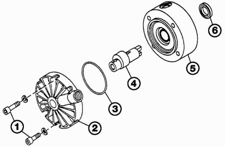
1 - bolts; 2 - cover; 3 - sealing ring; 4 - rotor; 5 - body; 6 - gasket
1. Using paint, mark the relative position of the cover and hydraulic pump housing (see fig. Hydraulic pump elements).
2. Unscrew the bolts securing the hydraulic pump cover, then remove the cover and O-ring and remove the pump rotor.
3. Check the condition of the hydraulic pump elements and, if necessary, replace them. Regardless of condition, replace cover O-ring and rotor gasket.
4. Using a flathead screwdriver, carefully pry the old rotor gasket out of the back of the pump housing. Install the new rotor gasket in place in the pump housing.
5. Lubricate the rotor gasket and rotor with clean hydraulic fluid and install the rotor in the housing.
6. Install a new o-ring on the pump cover, then install the cover with o-ring on the pump body. Install the cover so that the marks made before removal are aligned. Fasten the pump cover with bolts, tightening them to the required torque.
Installation
1. Fit a new o-ring to the rear of the hydraulic pump and install the pump to the cylinder head, aligning the lug on the pump rotor with the camshaft groove.
2. Screw in the pump mounting bolts and tighten them to the required torque.
3. Connect the hose and tube to the pump. At the same time, install gaskets on both sides of the hose coupling. Secure the hose and tube with a connecting nut and bolt, tightening them to the required torque.
4. Fill the hydraulic system with fluid.
Hydraulic pump on 6-cylinder petrol and turbo diesel models
On models with 6-cylinder petrol and turbocharged diesel engines, a combined hydraulic pump is installed, which simultaneously works in the power steering system and the self-levelling rear suspension system.