
After disassembling the head and with high mileage, be sure to replace the oil seals.
Attention! If valve control parts are to be used again, they must be reinstalled. In order not to confuse them, we recommend providing a storage panel.
Removing
1. Disassemble the chain tensioner.
2. Remove the camshaft.
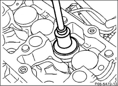
3. Remove the poppet using a rubber siphon (diameter 30 mm), for example, HAZET 735-2. Do not use a magnetic siphon: this will magnetize the sliding surface of the poppet pusher, and tiny metal chips will be deposited on it, which will damage the poppet pushers and cams. The siphon can be made independently using a suction cup and a wall hook.
Attention! Before removing the pusher, thoroughly clean its surface.
Attention! When the valve spring is compressed, the corresponding piston must be in the ignition TDC position. Since cylinder 1 is at TDC when the camshaft is removed, it is advisable to start by removing the cylinder 1 valve springs.
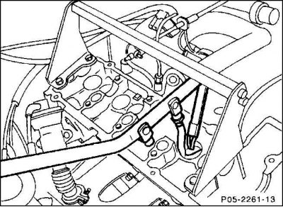
4. Screw the support bridge for the lever pusher to the cylinder head.
5. Push down the inlet and exhaust valve spring plates of cylinder 1 with the lever pusher. Cylinder 1 is on the front side of the control chain, cylinder 4 is on the rear side of the flywheel.
6. Remove crackers with tweezers or a magnet (202).
7. Slowly decompress the valve spring (198).
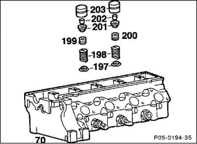
8. Remove the spring plate (201) and a spring. (203) poppet pushers, (197) lower valve springs.
9. A repair shop for high mileage engines can check the strength of the valve springs.
10. Remove the second valve spring for cylinder 1.
11. Oil seals (199–200) remove with a special collet, eg HAZET 791-6.
Attention! Be careful not to damage the valve stem and valve guide.
12. Remove burrs from the undercut of the valve stem.
Attention! Replace pressed valve cotters and spring plates. With dismantled valve springs, spring plates and crackers, the engine must not be rotated, since the valves rest on the pistons and may fall into the cylinder.
Installation
Inlet valve oil seal (199)
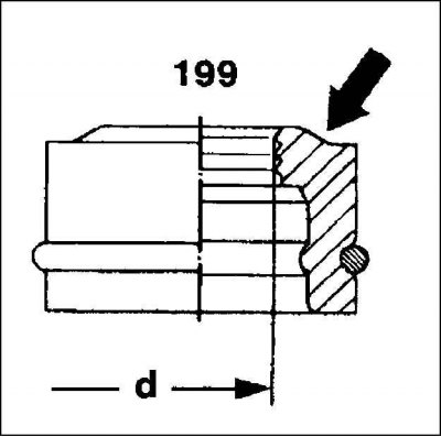
Chamfer (arrow) shifted.
Inner diameter d = 7.3 mm.
Wire ring phosphated, black.
Exhaust valve seal (200)
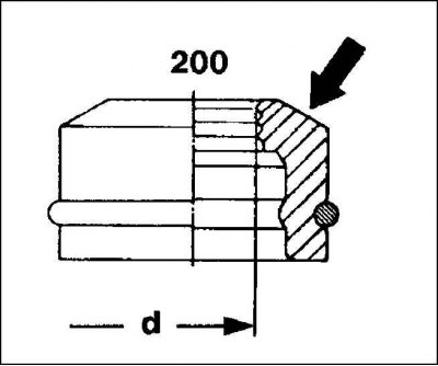
Chamfer (arrow) bevelled.
Inner diameter d = 8.2 mm.
Wire ring galvanized, yellow.
1. Lubricate the new oil seals with oil and use a mounting mandrel, eg HAZET 2577, to install on the stem.
Attention! Do not mix up the exhaust and intake valve caps.
2. Install the valve springs from below according to their color.
3. Put on the plates of the valve springs and press them from below, insert the crackers into the corresponding grooves on the valve stems.
4. Set the next piston to TDC and replace the slinger caps by turning the engine 1/2 turn by the crankshaft belt pulley center bolt until the notch indicating 180°is under the pointer on the crankcase. Thus, the piston of the third cylinder is at the ignition TDC (firing order of cylinders 1–3–4–2). Then pistons 4 and 2 are set to the TDC position by a corresponding turn of half a turn.
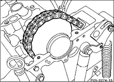
Attention! Raise the control chain as the engine rotates so that it does not retract inward. In the workshop, a special support wheel for the control chain is used for this.
5. Install poppets and camshaft.
6. Install the chain tensioner.