
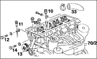
Cylinder head bolts (engine 2.5 l)
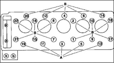
A - bolt with shoulder M 10x115
B - bolt with shoulder M 10x102
a - universal bolt M 8 x 50 (chain case)
b - bolts M 8 x 80 (for fuel filter)
Attention! The picture refers to the 2.5L engine (22 bolts). For a 2.2 liter engine with 18 bolts in the cylinder head, the same sequence of actions.
The cylinder head is disassembled only on a cooled engine. The outlet and suction pipe outlets remain connected. Signs of a defective cylinder head gasket are the same as described for a 2 liter engine.
Removing
1. Raise the engine hood.
2. Disconnect the wire "masses" batteries (–).
Attention! This erases the anti-theft code of the radio.
3. Raise the car at the front and remove the bottom cover of the engine compartment.
4. Drain the coolant.
5. Unscrew the front exhaust pipe from the exhaust manifold.
6. Unscrew the exhaust pipe from the side holder.
7. Unscrew the fan hydraulic clutch.
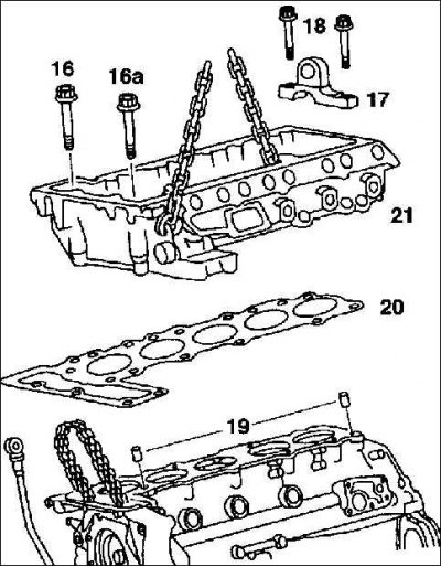
8. Loosen and remove the V-ribbed belt.

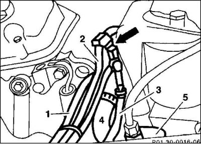
9. Disconnect vacuum hoses (2, 3) from the vacuum pump (5) and distributor parts (arrow). If necessary, first loosen and move back the hose clamps.
10. Remove the air bleed hose from the cooling system (1) and the coolant hose, after loosening the hose clamps.
11. Remove the hose connecting the air filter.
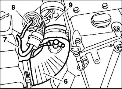
12. Disconnect vacuum hoses (7) And (8) from the vacuum tank, pressure regulator flap and exhaust recirculation valve.
13. Disconnect the wires from the temperature switches on the left side of the cylinder head and coolant flange.
14. Remove camshafts.
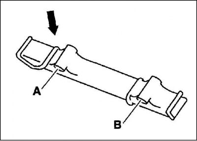
15. Remove the top fingers (14) control chain guide bar (15) using an ejector (2) and M6 studs. If no such tool is available, the pins can be removed using a ten-tooth chain sprocket (square length = 1/2 inch) and an M6 bolt, having approximately three times the length of the sprocket, and a locknut. To do this, screw the locknut onto the M6 bolt and insert a washer on top of the bolt. Place the sprocket on the pin, screw the M6 bolt into the thread of the pin and tighten the locknut until it contacts the surface of the sprocket. The spacer washer serves to improve surface contact. Pull out the pin while holding the head of the bolt with a wrench while turning the locknut with the wrench relative to the sprocket.
16. Also remove the lower pins of the guide bar below the coolant connection.
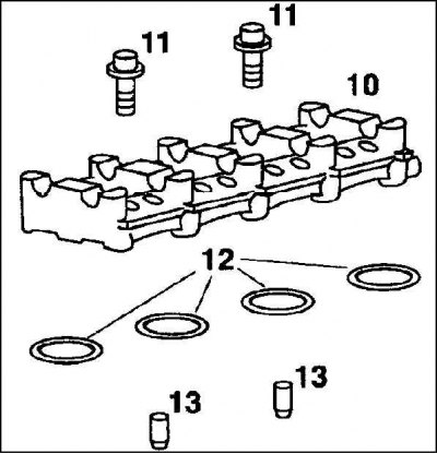
17. Unscrew the camshaft housing (10) and take it off. The poppets do not need to be removed: they will not fall out, thanks to the lower protrusions.
Attention! Pay attention to the two mounting sleeves (13). O-ring (12) when reinstalling, replace with a new one.
18. Remove the fuel line injectors.
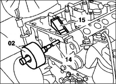
19. Unscrew the guide tube of the oil level gauge (10) for automatic transmission (if she is) from the cylinder head at the rear right.
20. Unscrew the dipstick guide tube (11) from the cylinder head.
21. Unscrew shock absorber (13) ribbed V-belt tensioner from the cylinder head.
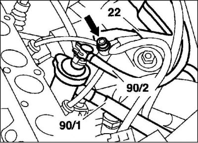
22. Disconnect the fuel lines (90/1) And (90/2) from the fuel preheater.
Attention! To facilitate subsequent installation, mark the fuel lines with adhesive tape. Collect spilled fuel with a rag.
23. Disconnect cable duct (22) from the fuel preheater.
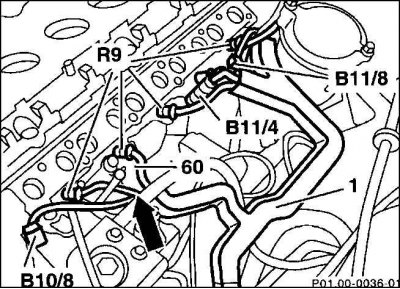
24. Unscrew the electrical wires from the glow plugs (R9), having previously marked the wires with adhesive tape.
25. Disconnect the plug connections from the coolant temperature sensor for the air conditioner (B10/8), display device (B11/4) and reheating (B11/8).
26. Unscrew cable duct (1) from fuel heat exchanger (60).
27. Disconnect the thick coolant hose from the rear of the cylinder head by fully opening the retaining clamp.
28. Remove the mounting bolts, remove the fuel filter with holder from the cylinder head and set aside with the attached fuel lines.
29. Remove the guide bar in the chain case in the same way as the top bar.
30. Remove the two M8 cylinder head bolts with a long socket wrench SW.
31. Remove the cylinder head bolts in the reverse order of their numbering, i.e. from 22 to 1 (see fig. Cylinder head bolts (engine 2.5 l)). To do this, first loosen all the bolts by 1/2 turn and then completely turn them out using a socket wrench, for example, HAZET 2751.
32. It is better to lift the cylinder head with two people. In repair shops screw the holder (17) instead of the outer cover of the bearing of the camshafts and hang a chain hoist to lift the cylinder head.
Installation
1. Before installation, clean the cylinder head with a scraper from the remnants of the sealant. Make sure they don't get into the holes.
2. Blow out the threaded holes, cleaned of oil and water, with compressed air. If there is no compressed air, then soak up the liquid in the blind holes with a rag wrapped around a small screwdriver.
3. Check the cylinder head and cylinder block for cracks and flatness with a steel ruler.
4. Be sure to replace the cylinder head gasket (20).
5. Apply a new gasket without sealant so that it does not block the holes.
6. Install the cylinder head (21).
Attention! Center the cylinder head with fixing sleeves (19) on the engine block.
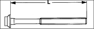
7. Measure length (L) cylinder head bolts. If the maximum length is exceeded (see table Cylinder head bolts), just in case, replace the bolt.
8. Lubricate the threads of the cylinder head bolts, as well as the place where they fit to it, with engine oil, screw in the bolts and tighten by hand (see fig. Cylinder head bolts (engine 2.5 l)).
Attention! The cylinder head bolts are mounted without washers. Carefully tighten the cylinder head bolts. First check the accuracy of the torque wrench.
Tighten the cylinder head bolts in sequence 1 to 22 and 1 to 18 respectively, in 4 steps.
Attention! The cylinder head bolts at each stage are tightened in sequence from 1 to 22 or from 1 to 18.
- Stage 1: with a torque wrench with a torque of 15 Nm.
- Stage 2: with a torque wrench with a torque of 35 Nm.
- Step 3: Using an open-end wrench, tighten the bolts in the same direction by 90°. Pause for a minute for the bolts to settle. Then tighten the bolts further without loosening.
- Step 4: Turn the bolts in the same direction 90°with an open end wrench.
Attention! When tightening the bolts, evaluate the angle of rotation. Position the wrench handle along the engine and tighten the bolt in one go until the wrench handle is across the engine (1/4 turn, 90°).
9. 2 bolts M8 (A) in front of the cylinder head, install with spring washers and tighten with a long socket wrench SW6 with a torque of 25 Nm.
10. Install the fuel filter with holder and tighten with a torque of 25 Nm, bolts (b).
11. Install the lower control chain guide bar in the chain case and insert the stop pins. At the same time, install the guide rail so that the mounting elements of the upper thrust pin (A) and bottom finger (IN) were on top.
12. Attach a thick coolant hose to the rear coolant inlet and secure with a hose clamp.
13. Connect electrical wires to glow plugs and coolant temperature sensors.
14. Screw the cable duct to the fuel preheating system.
15. Connect with a torque of 25 Nm the shock absorber of the ribbed V-belt tensioner to the cylinder head.
16. Screw the dipstick guide tube in the engine and in the automatic transmission to the cylinder head.
17. Install injectors.
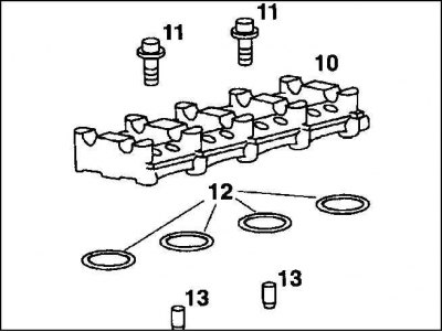
18. Install the camshaft housing with poppets and center with two balancing sleeves (13).
Attention! O-rings (12) between the cylinder head and the camshaft housing must always be replaced with new ones. Fasten two bolts (11) with a moment of 15 Nm.
19. Install the top control chain guide bar, drive in the stop pins.
20. Install the camshafts and cylinder head cover.
21. Install the air filter hose.
22. Attach 2 vacuum hoses to the vacuum tank of the pressure regulator flap and the EGR valve.
23. Slip the wire over the temperature switch on the left side of the cylinder head to the coolant flange.
24. Put on vacuum hoses (2, 3) to the vacuum pump (5) and distributor part (arrow), secure the hoses with clamps.
25. Install the coolant deaeration hose (1) and coolant hose (4) and secure with clamps.
26. Install the ribbed V-belt.
27. Attach and adjust the throttle cable.
28. Install the hydraulic fan clutch.
29. Screw the front exhaust pipe to the manifold and side brackets.
30. Fill with coolant.
31. Connect cable "masses" (–) to the battery.
Attention! If the cylinder head gasket was defective, the engine oil and oil filter should be replaced.
32. Bring the engine up to operating temperature and check the tightness of all connecting elements.
33. Establish the lower cover of a motor compartment and fasten with bolts.
Attention! Tightening the cylinder head bolts is prohibited.
34. To close the engine hood, press the release button on the left bracket.
Cylinder head bolts
| Thread diameter | Length in new position | Maximum length |
| M 10 | 102.0 mm | 104.0 mm |
| M 10 | 115.0 mm | 117.0 mm |