
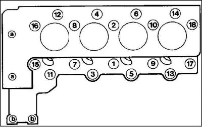
Location of cylinder head bolts
Remove the cylinder head only when the engine is cold. In this case, the exhaust manifold is not removed.
A defective cylinder head gasket is recognized by one or more of the following:
- power loss;
- coolant leak, white exhaust gas when engine is warm;
- oil leak;
- coolant in the engine oil, the oil level does not decrease, but increases, shreds of foam on the oil level indicator; gray color, dilution of engine oil;
- engine oil in the coolant;
- the coolant boils strongly;
- lack of compression in two adjacent cylinders.
Removing
1. Raise the hood.
2. Disconnect the wire "masses" batteries.
Attention! This erases the anti-theft code of the radio.
3. Remove the air filter.
4. Remove the cross tube and air filter suction hose.
5. Drain coolant.
6. Remove the radiator.
7. Loosen the ribbed V-belt and remove it.
8. Remove the ribbed V-belt tensioner.
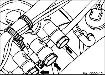
9. Clamp the fuel lines in the fuel filter holder with hose clamps.
Attention! To facilitate subsequent installation, mark the fuel lines with adhesive tape. Clean up any spilled fuel with a rag.
10. Unscrew the two mounting bolts of the holder and remove the holder with the fuel filter.
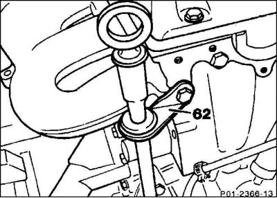
11. Unscrew holder (62) guide tube of the oil level meter.
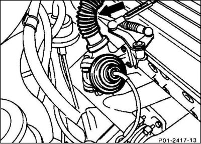
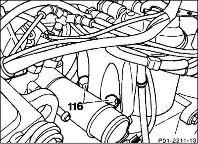
12. Remove hose from outlet recirculation valve (arrow), leading to the air duct housing.
13. Remove the hose between the exhaust recirculation valve and the intake pipe.
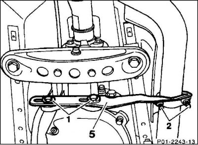
14. Unscrew the side support (5) gearboxes (1) and exhaust pipe (2).
15. Unscrew the front exhaust pipe from the manifold.
16. Remove nozzles.
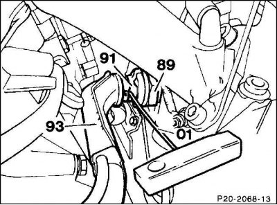
17. Remove the retainer (91) heating supply line with a homemade hook (01).
18. Unscrew pipe outlet (93) from the oil filter and remove from the nozzle (89).
19. Unscrew the electrical wires from the glow plugs, having previously marked with adhesive tape.
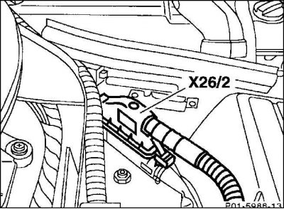
20. Remove the 36-pin connector (Х26/2).
21. Remove the intake manifold.
22. Remove the cylinder head cover.
23. Set the engine to the TDC position of the ignition of the first cylinder.
24. Disassemble the chain tensioner.
25. Remove the camshaft by marking the position of the control chain and timing gear with varnish or a chisel.
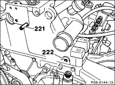
26. Knock out two fingers (221) And (222) using an M6 threaded stud and an ejector.
27. If there is no such tool, then you can remove the fingers using a chain sprocket with ten teeth (square length - 1/2 inch) and an M6 bolt, which has approximately three times the length of the sprocket. To do this, screw the locknut onto the M6 bolt, then install the washer on it. Put the sprocket on the pin, screw the M6 bolt into the thread of the pin and tighten the locknut until it touches the sprocket. The spacer washer serves to improve the fit of the surfaces. Pull out the pin while holding the head of the bolt with a box wrench while turning the locknut with an open end wrench against the sprocket.
28. Remove the control chain guide bar.
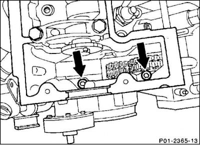
29. Remove the two M8 cylinder head bolts using a long socket wrench SW 6.
30. Unscrew the cylinder head bolts in the reverse order of their numbering, i.e. from 18 to 1 (see pic. Location of cylinder head bolts). To do this, first unscrew all the bolts by 1/2 turn and then completely unscrew them using a socket wrench, e.g. HAZET 2751.
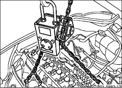
31. Raise the cylinder head, e.g. with a crane. The attachment points for the lifting cable are the lug at the front left and the outlet of the exhaust manifold at the rear right.
Installation
1. Clean the sealing surface of sealant residues with a suitable scraper. Make sure that dirt does not get into the holes of the motor block. Cover the holes with a cloth.
Attention! The cylinder head bolt holes must not be clogged with oil and coolant residues. Blow out the holes with compressed air or clean with a screwdriver wrapped in a rag, and suck out the liquid. Otherwise, when tightening new bolts, pressure will build up, which can lead to cracks in the engine block or incorrect tightening of the bolts.
2. Check the flatness of the motor block.
3. Apply a new cylinder head gasket without sealant to the degreased sealing surface so that the holes are not blocked.
4. Clean the sealing surface of the cylinder head.
5. Check the flatness of the block head.
6. Install the cylinder head.
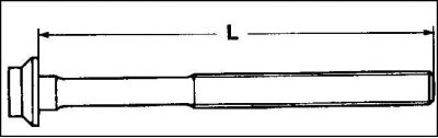
7. Measure length (L) cylinder head bolts. If the maximum length is exceeded (see table Cylinder head bolts), never use such bolts.
8. Lubricate the threads and the surface adjacent to the bolt head with engine oil. Check bolts for cracks and replace if necessary. Screw the bolts into the cylinder head and hand tighten (see table Location of cylinder head bolts).
Attention! The cylinder head bolts must be installed without shims. Tighten the bolts carefully. Check the accuracy of the torque wrench first.
The cylinder head bolts are tightened in sequence from 1 to 18 in four stages (see pic. Location of cylinder head bolts).
Attention! The cylinder head bolts at each stage are respectively tightened in sequence from 1st to 18th.
First stage: with a torque wrench with a torque of 15 Nm.
Second stage: with a torque wrench with a torque of 35 Nm.
Step 3: Using an open end wrench, tighten the bolts in the same direction by 90°.
Attention! At this point, take a 10-minute pause in tightening the bolts. Then continue to tighten the bolts without loosening them.
Step 4: Use an open end wrench to tighten the bolts an additional 90°.
Attention! When tightening the bolts, hold the wrench handle along the engine and turn it in one motion until the handle is across the engine (1/4 turn = 90°).
9. For two M8 bolts (A) in front of the cylinder head, install elastic washers and tighten with a long socket wrench SW6 with a torque of 25 Nm.
10. Install the control chain guide bar, insert the pins, having previously lubricated their shoulders with a sealing compound, for example, Mercedes-001 589 2520.
11. Install the camshaft.
12. Install the chain tensioner.
13. Set the engine to the ignition TDC position and check the position of the camshaft.
14. Install the cylinder head.
15. Install the intake manifold.
16. Install the 36-pin connector.
17. Screw on the electrical wires of the glow plugs.
18. Install the pipe elbow with a new O-ring and screw the pipe elbow to the air filter.
Attention! The O-ring can be lowered into the coolant to improve installation. Never use grease or oil.
19. Install the heating supply line and put on the fixing clips.
20. Screw the front exhaust pipe to the manifold with a torque of 25 Nm.
21. Screw with a torque of 25 Nm the holder of the gearbox and the front exhaust pipe.
22. Install the hose from the EGR valve to the air line housing, and the hose between the EGR valve and the intake pipe.
23. Screw on the oil dipstick guide tube holder.
24. Install the fuel filter with holder and screw to the cylinder head with a torque of 25 Nm.
25. Screw the fuel lines with new gaskets to the fuel filter. Remove hose clamps.
26. Install the ribbed V-belt tensioner.
27. Fit and tension the ribbed V-belt.
28. Install the radiator.
29. Install the air filter cross tube and air suction hose.
30. Install the air filter.
31. Fill with coolant.
32. Connect wire to battery "masses" (–).
33. Set the clock.
34. Set the radio's anti-theft code.
Attention! If the cylinder head seal was defective, change the engine oil and oil filter.
35. Warm up the engine to operating temperature and check the tightness of all connection elements.
Attention! Tightening the cylinder head bolts is prohibited.
36. Finally, press the engine hood release button on the left bracket.
Cylinder head bolts
| Thread diameter | Length for new installation | Maximum length |
| M 10 | 80.0 mm | 83.6 mm |
| M 10 | 102.0 mm | 105.6 mm |
| M 10 | 115.0 mm | 118.6 mm |
Location of cylinder head bolts
| Bolt size | Hole No |
| M 10–80 | 3, 5, 11, 13 |
| M 10–102 | 2, 4, 6, 8, 10, 12, 14, 16, 18 |
| M 10–115 | 1, 7, 9, 15, 17 |
| M 8–30 | a (chain case area) |
| M 8–80 | b (fuel filter) |