
Removing
Attention! If valve control parts are to be reused, they must be reinstalled. To avoid confusion, make a special panel for storing them.
1. Remove camshafts.
2. Remove the camshaft housing.
3. Remove nozzles.
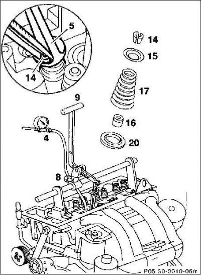
4. Remove the sheath for the engine wiring kit from the front wall of the body.
5. Screw the support baffle with the movable part of the lever pusher to the cylinder head. To do this, you can use the camshaft housing bolts (М7х42).
6. Using a wrench with a socket, set the piston of the corresponding cylinder to the TDC position. 4-cylinder engine: when the pulley is at TDC, the pistons of cylinders 1 and 4 are at TDC. If the 180°mark of the belt pulley coincides with the mark on the crankcase, the pistons of cylinders 3 and 4 are in the TDC position.
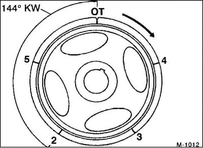
7. 5-cylinder engine: at the TDC position of the belt pulley, the piston of cylinder 1 is in dead center. After turning the crankshaft through an angle of 144°, respectively, the piston of the next cylinder in the sequence is set to TDC (1–2–4–5–3). Note: It is possible, for example, to mark the belt pulley with four additional markings, each at a distance of 72°. After replacing the oil seals of the 1st cylinder, rotate the crankshaft until mark 2 is opposite the mark on the crankcase. In this case, the piston of cylinder 2 will be set to TDC. Replace oil seals of the 2nd cylinder. Then crank the engine up to the mark (4). Now the piston of the 4th cylinder will be at TDC. Thus, it is possible to sequentially install the pistons at TDC.
8. The TDC position of the corresponding cylinder can also be set using an electrode wire. To do this, thread the electrode wire into the nozzle hole of cylinder 2 (piston of cylinder 2 is at TDC). With an assistant, slowly turn the crankshaft in the direction of its rotation and monitor the position of the wire during rotation. As soon as the wire reaches the highest position, the piston is set to TDC.
Attention! Hold the control chain high as the crankshaft rotates to prevent it from jamming.
9. Hang the lever pusher (9).
10. Lock the crankshaft by shifting into first gear and applying the parking brake.
11. In the compression chamber of the cylinder, pressurize at least 5 bar (about 5 atm.). To do this, screw in the connecting hose (4) cylinder tightness control device with a connecting piece Mercedes-604 589 006300 into the prechamber (nozzle hole).
12. Maintain an overpressure of at least 5 bar in the cylinder through a compressed air hose.
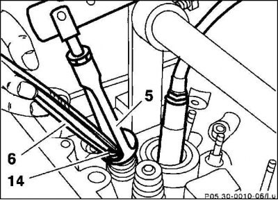
13. Install pressure piece (5) lever pusher (9) on the valve spring plate. Orient the pressure and moving parts parallel to each other. Fix the moving part with a bolt (8).
14. Remove the valve spring.
Attention! Do not remove the valve spring without using compressed air, otherwise the valve and piston may be damaged.
15. Remove the valve stem parts from the valve stem (14) with tweezers or a magnet.
16. Remove the valve disc (15) and valve spring (17).
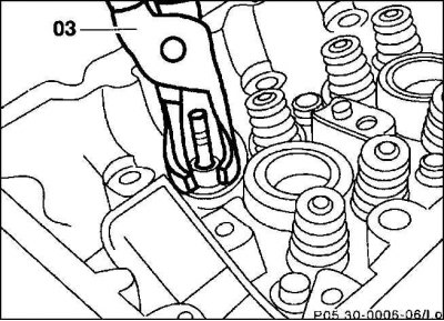
17. Remove the oil seal from the valve stem (16) with a special collet (03), for example, HAZET 791-6.
Attention! Do not damage the valve stem and valve guide!
18. Remove the lower spring plate (20) and check for damage, replace if necessary.
19. If necessary, clean the groove of the rod with a fine-grained emery cloth.
20. Check the wear of the valve guides in the area where the caps are attached to them. If a tight fit of the oil seals is not ensured, their guides should be replaced (repair shop job).
Installation
1. Replace the pressed-in parts of the valve stem and valve spring caps with new ones.
2. Valve guides with loose rings on valve stem seals need to be replaced (repair shop job).
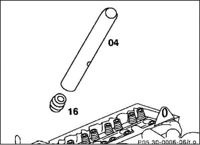
3. Oil cap (16) valve stem and manually insert using the mounting mandrel (04).
4. Install the valve spring and poppet and compress the valve spring.
5. Install the valve stem parts and decompress the valve spring.
6. Replace the caps on the other valve stems in the same way.
7. Release compressed air.
8. Install the camshafts.
9. Install injectors.
10. Install the camshaft housing.
11. Attach the engine wire sheath to the front wall of the body.